Lab Network in GNS3
Preamble/Life Story
Once upon a time this was a network that was run using a passively-cooled 6-port PC I bought off AliExpress running pfSense and a managed network switch. However as time went on I wanted to make my lab network a self-contained one that could be run on a single machine and leave the AliExpress PC and switch for my production network.
So in the December holidays of 2024 (specifically 2024-12-03 according to the README in the GNS3 project) when I had a lot of downtime on my hands I started work on replicating my production network in GNS3 with some twists:
- Use OPNSense instead of pfSense since pfSnese appeared to have been silently killing support for their community edition (one or more updates have since been released).
- Have redundancy for the core and firewalls.
- Instead of using firewall rules for inter-VLAN traffic, I want to do this in the core switches (boy did I regret that).
- Routing between VLANs will also be done in the core switches instead of the firewall.
Another motivation for this is I needed to learn some of this anyway for work, so if I want to learn it for myself anyway, why not do it for my own project in my own time and then I can just carry that knowledge over.
Completed
- Many alises and firewall rules exist that were likely carried over from the old firewall and are now defunct. These should be removed.
- Prune firewall rules to be only those that work and/or fix broken ones.
- Add firewall rule to block traffic from windtunnel1 to LAN; this doesn't need to be done on the switches.
- This is already handled by the ACLs on the cores.
- Fix DHCP: the router is responding to the requests but clients aren't receiving them and the router is setting itself as the default route instead of the cores. See DHCP section.
- Maybe run DNS on these firewalls?
- Can't run DNSSEC on firewalls but after reviewing the DNS records on simonforgets I found that the zone for digitaldoggo.conorab.com could be removed entirely.
- This zone (and every zone besides the one needed for the AD domain) has been backed up and removed from simonforgets including the DNSSEC keys.
- The LAN inteface of router1-2 does not have an IPv6 address so IPv6 is not highly available.
- There is no OpenVPN server on these firewalls. Add one.
- Check if ports 3 and 4 on sw-core1-1 should be edge ports.
- They shouldn't.
- Add addition of IPv6 addresses to CARP and to the LAN of router1-2.
- Add change to OpenVPN configuration where the CARP binding is now pointing to LAN instead of WAN.
- Add modified ACLs.
Previously No Fix
- The PureVPNDedicated1 interface is not highly available and needs to be manually switched.
- This may be a bug in OPNSense: https://github.com/opnsense/core/issues/10392
- There are CARP scripts to handle this kind of situation but it looks like these are not synced with pfSync.
- Because of this, it will not be fixed as it would be a janky workaround.
- Changing CARP dependency to LAN fixed the issue.
Network Diagram
Normal pre-temporary jump-host configuration:
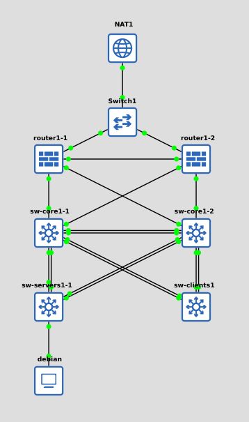
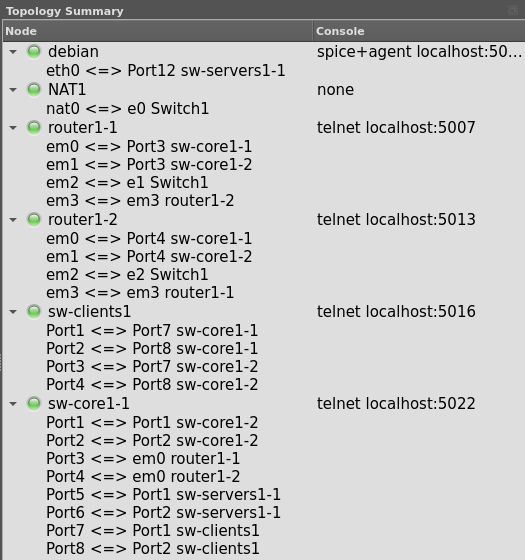
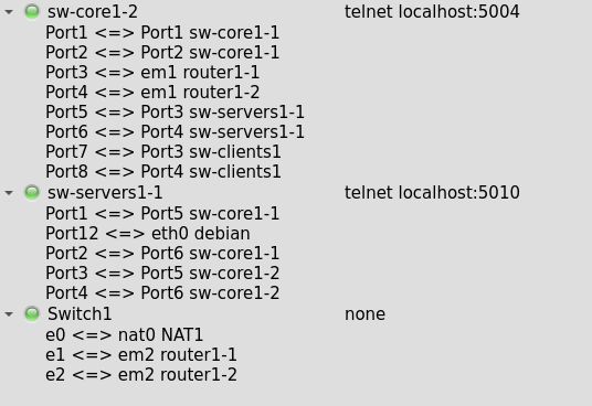
- Router1-1 and Router1-2 connect to the Internet via a dumb switch..
- Router1-1 and Router1-2 connect to each other directly for pfSync in order to detect when the other has gone offline and take over.
- Router1-1 and Router1-2 independently connect to sw-core1-1 and sw-core2-2.
- The core switches connect to all other switches using 2 links per switch configured with LACP. This is for a mix of having redundancy and to increase uplink speeds.
- This is a kind of minimal viable topology with 2 cores switches using VRRP for HA, 2 routers using CARP and pfSync in HA, 1 client switch and 1 server switch.
- debian is a testing VM.
Aliases
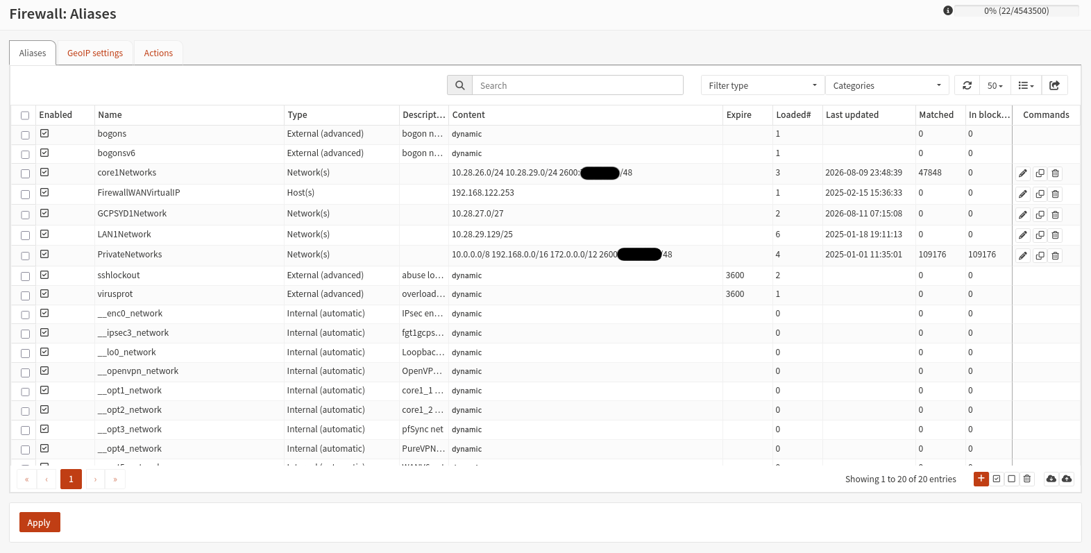
Aliases are placeholders that can be re-used in different parts of the OPNSense configuration. One use case is that instead of having to enter the IP address if your DNS server in a firewall rule and NAT independently, you can instead create an alias which points to that IP, and configure that alias in the firewall and DNS rules instead. This also means that the rules update automatically if you change where the alias points to.
The manually defined aliases on these firewalls are as follows:
Firewall High Availability
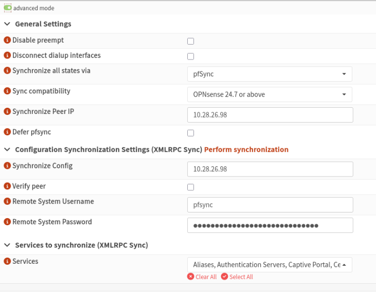
High Availability is configured between two firewalls that have a direct link to each other to ensure that if one goes down, then the other will (mostly) be able to take over automatically:
Primary:
Secondary:
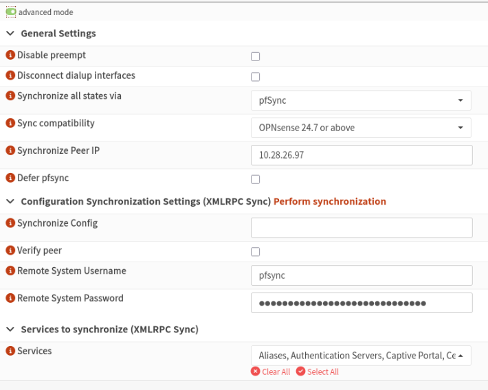
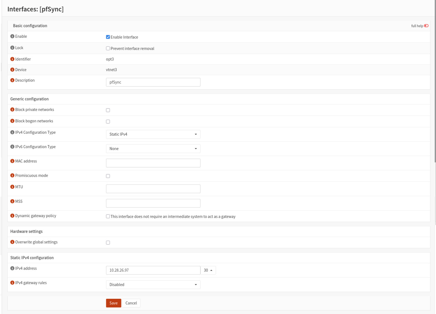
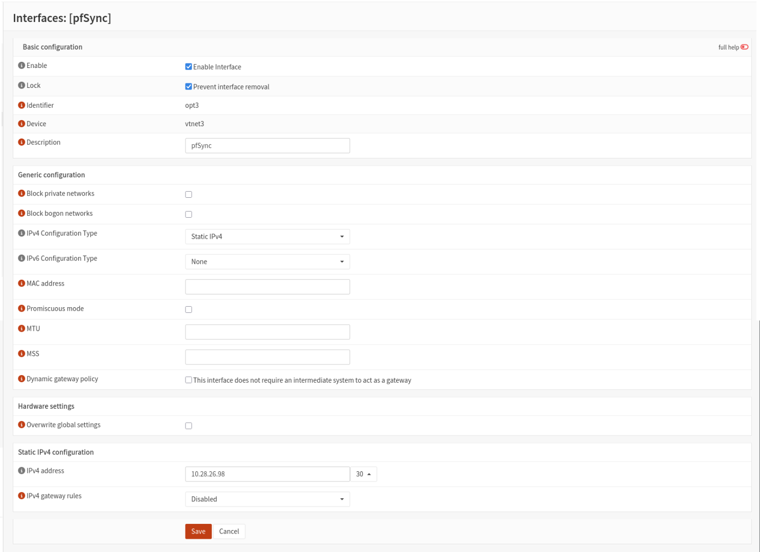
The link going directly between router1-1 (Primary) and router1-2 (Secondary) is the link used by the routers to check if the other is still online.
router1-1 Interface Configuration:
router1-2 Interface Configuration:
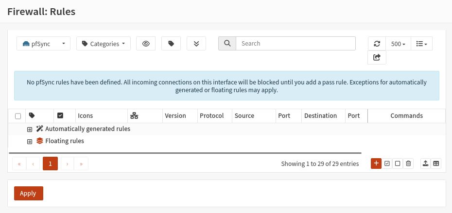
pfSync firewall configuration (excluding floating rules):
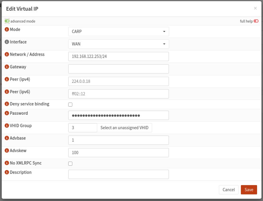
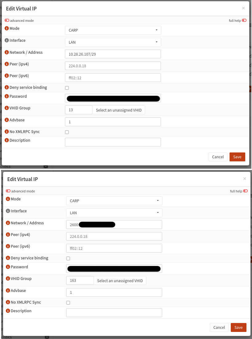
Each firewall has a unique IP on the WAN and LAN side, but this create a problem since you ideally you'd only configure a single gateway on the cores instead of having to add both the primary and secondary firewall IPs. To have the firewalls share an IP (1 for the WAN and 1 for the LAN) we use Virtual IPs:
WAN configuration:
LAN configuration:
In the VIP status page shows that this firewall (router1-1) is currently the primary and is responding to requests on the shared IP:
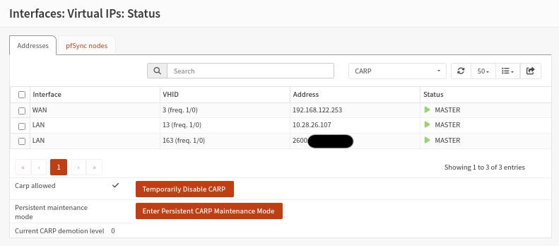
In this instance the WAN VIP is 192.168.122.253, and the LAN VIP is 10.28.26.107 for IPv4 and 2600:[REDACTED] for IPv6.
VIPs aren't just useful for routing, they can also be used for many of the services which run on OPNSense such as DNS, meaning if OPNSense is configured correctly you also end up with a highly available DNS server.
DHCP Server
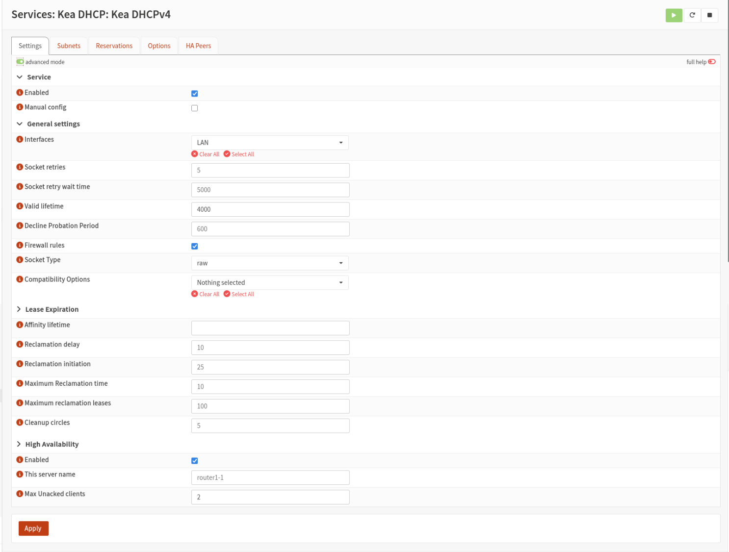
- The DHCP server runs on the routers using Kea DHCPv4.
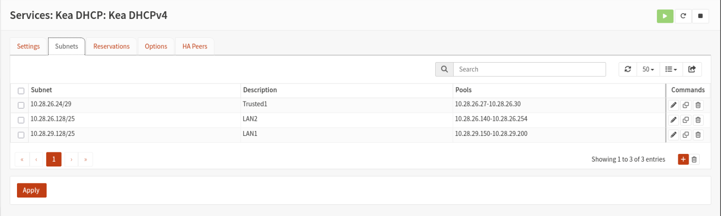
- The core switches are configured as DHCP relays which forward DHCP requests to the routers from other VLANs and then send the responses back.
- The DHCP servers are also highly available meaning either router can takeover if the other goes down.
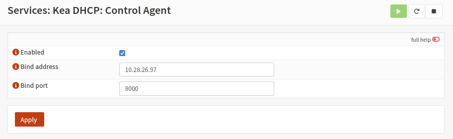
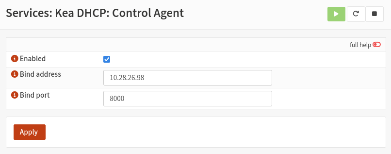
Control Agent:
The firewalls synchrnise DHCP leases and HA pulses over the pfSync link, hence the control agent IP being the same as the pfSync IP of each router:
Settings:
Subnets:
Reservations: There are no DHCP reservations configured.
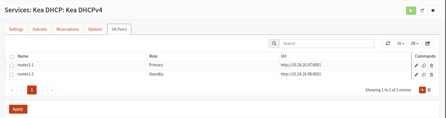
HA Peers:
Internet via OpenVPN with Dedicated IP
I paid for a dedicated IP VPN from PureVPN years ago for multiple reasons relating to my ISP at the time (Optus):
- Static IP so I don't need to use dynamic DNS to make sure my DNS records are pointing to my new IP address every time it changes.
- Some inbound ports like 80/tcp and 443/tcp were blocked by my ISP making it unsuitable for running any web servers.
- Some outbound ports like 25/tcp and SNMP were blocked by my ISP.
- Being able to browse the Internet from an IP that is different to what your servers are on and it publicly tied to your name is good for privacy.
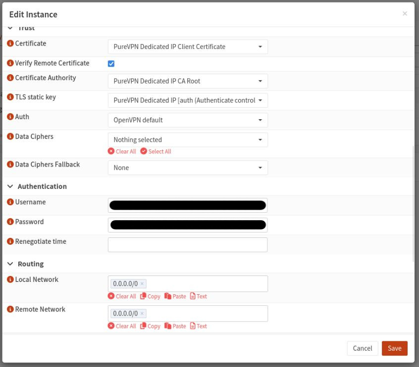
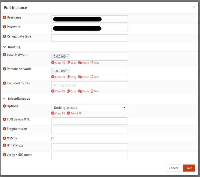
The firewalls are configured to connect to this VPN using OpenVPN and autostarts on whichever router is currently the primary.
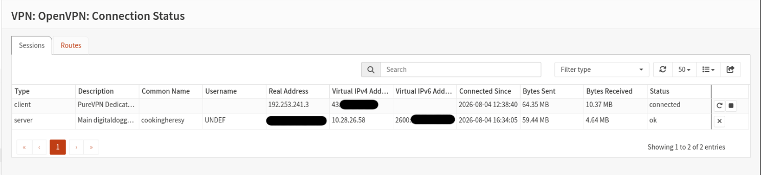
The VPN is configured as follows:
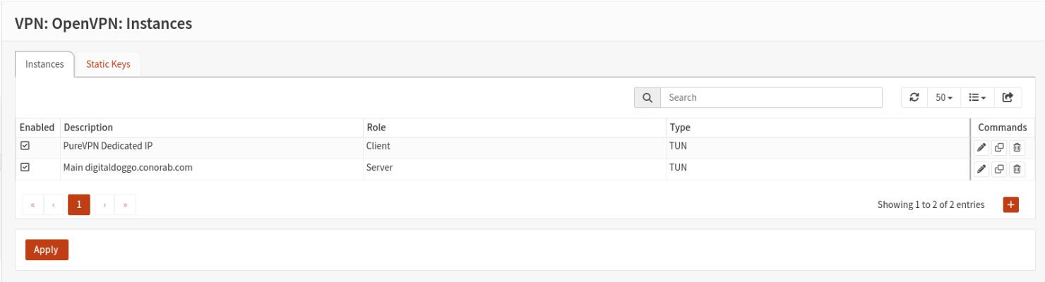
All instances:
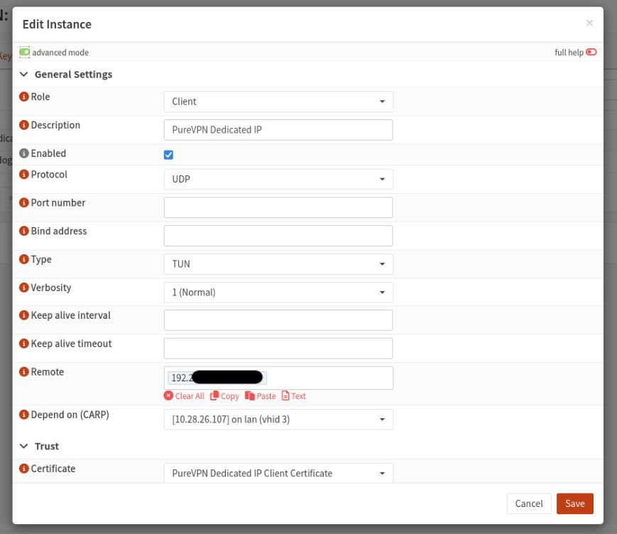
PureVPN instance configuration:
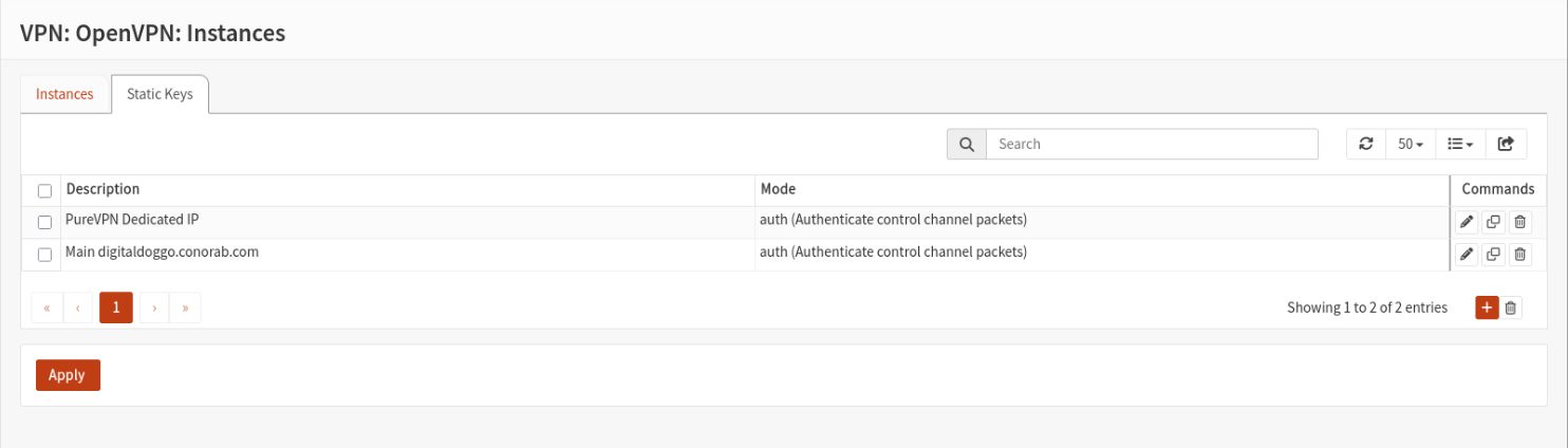
All OpenVPN static keys:
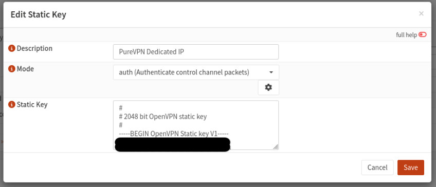
Static key used for authentication for PureVPN:
Interface configuration:
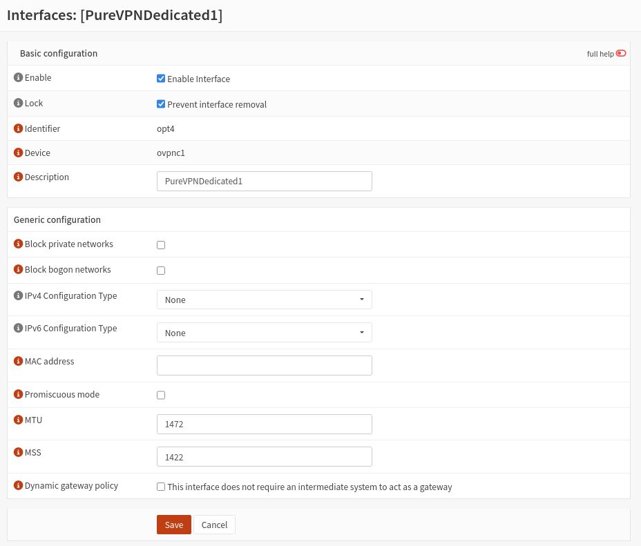
Firewall configuration (excluding floating rules):
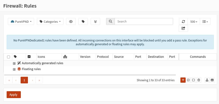
Floating firewall rules and routes will be covered in a later section as these overlap with other interfaces.
OpenVPN Server
- The OpenVPN server is configured to listen on IPv4 and IPv6 and provides and provides both IPv4 and IPv6 IPs to clients.
- The IP range used by clients is referred to as "Remote Access" in other parts of the configs.
- Both the server and clients are signed by an intermediate certificate which itself is signed by a root CA; the configuration requires certificate depth to be set to 2 as a result.
- Password authentication is not used; only certificate authentication.
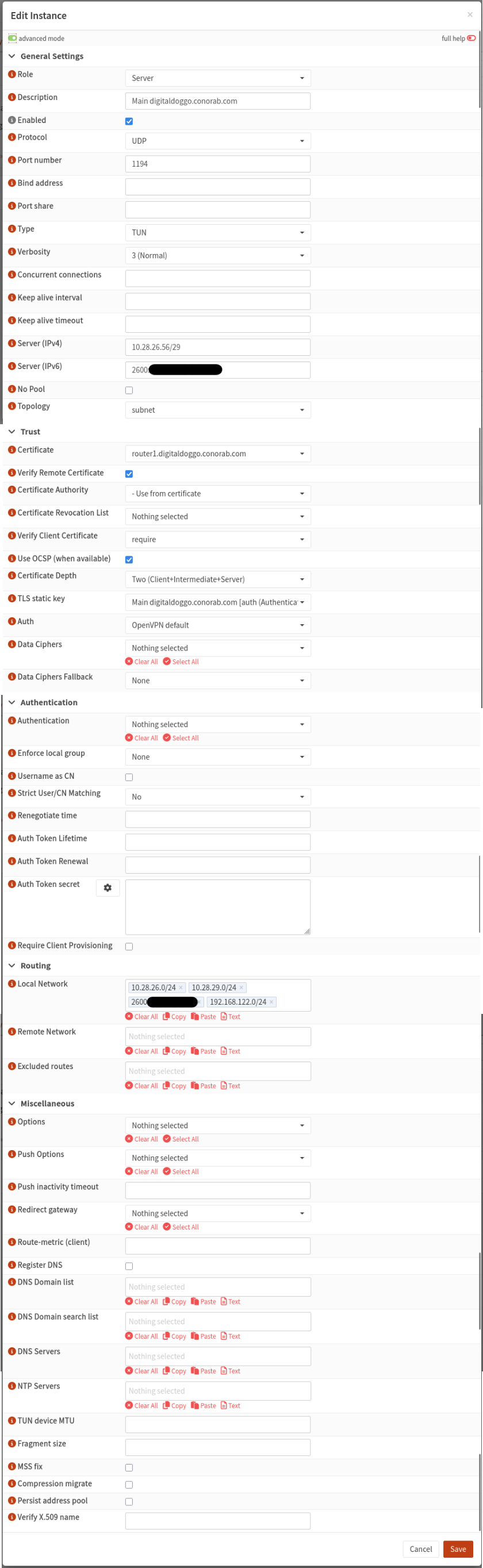
WAN Configuration on Firewalls
Each firewall has a WAN interface with its own IP:
router1-1 Interface Configuration:
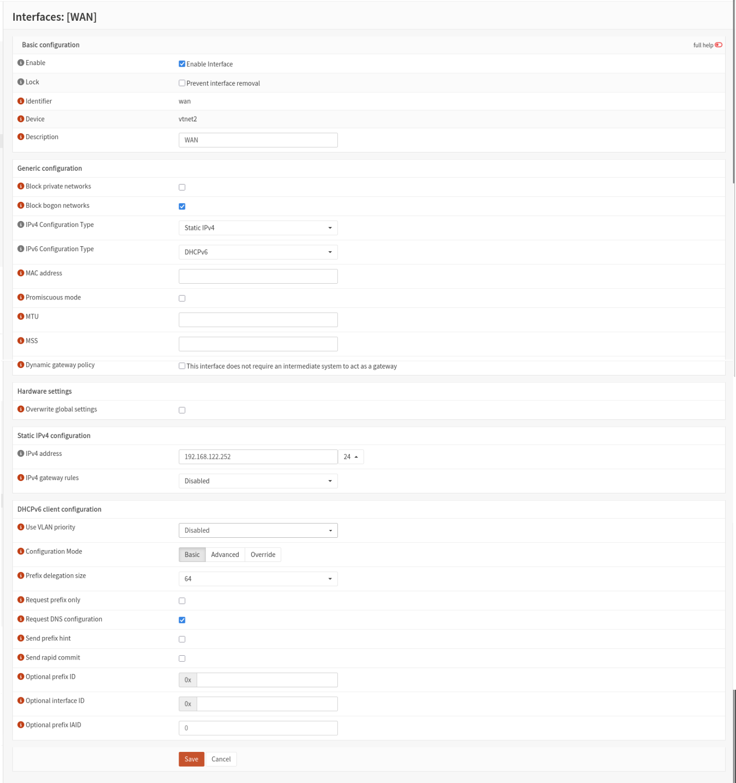
router1-2 Interface Configuration:
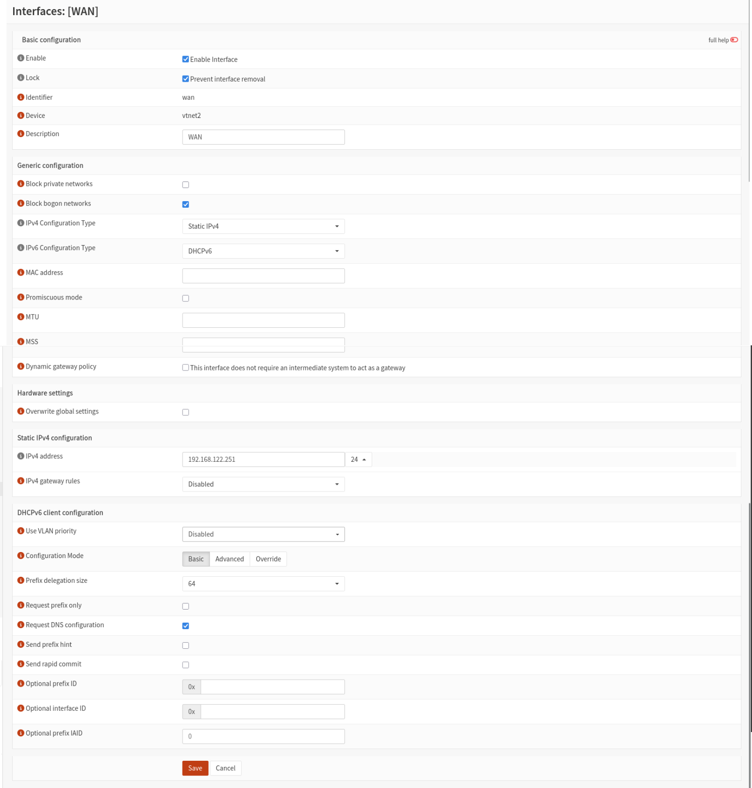
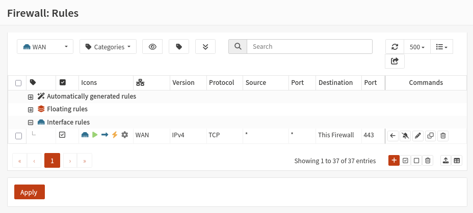
Firewall configuration (excluding floating rules):
WAN6 Configuration
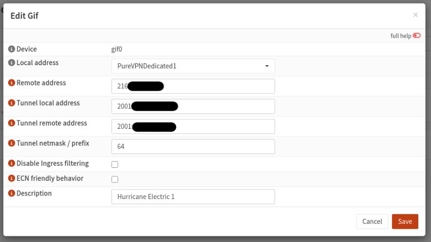
Both firewalls are also configured to connect to Hurricane electric for IPv6 access using tunnelbroker.net over a GIF tunnel which gives the firewalls their own IPv6 address as well as a /48 which can be handed out to clients on multiple subnets; each subnet getting a /64.
All GIF tunnels:
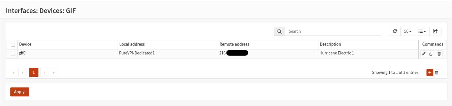
Hurricane Eletric GIF Configuration:
Interface configuration:
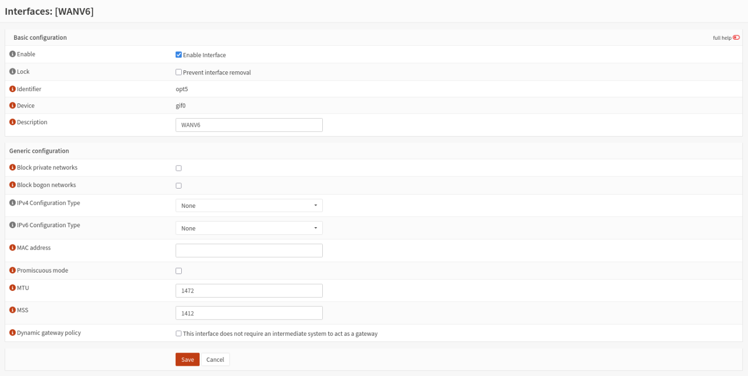
Firewall configuration (excluding floating rules):
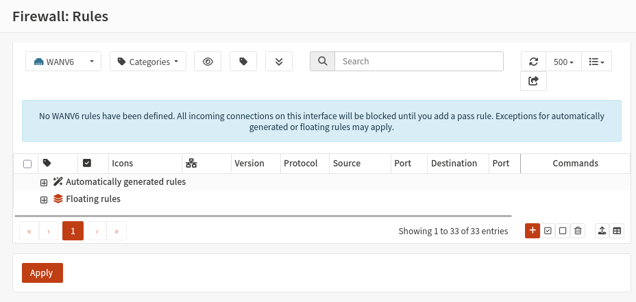
See NAT Firewall Configuration for how NAT is configured on this interface.
LAN Configuration on Firewalls
Each firewall has a LAN interace with its own IP:
router1-1 Interface Configuration:
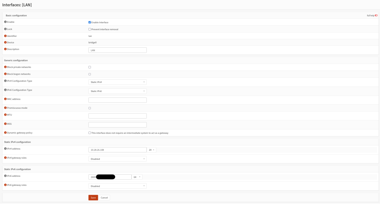
router1-2 Interface Configuration:
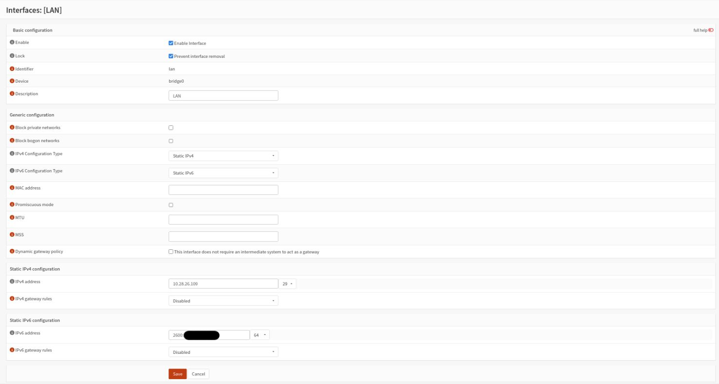
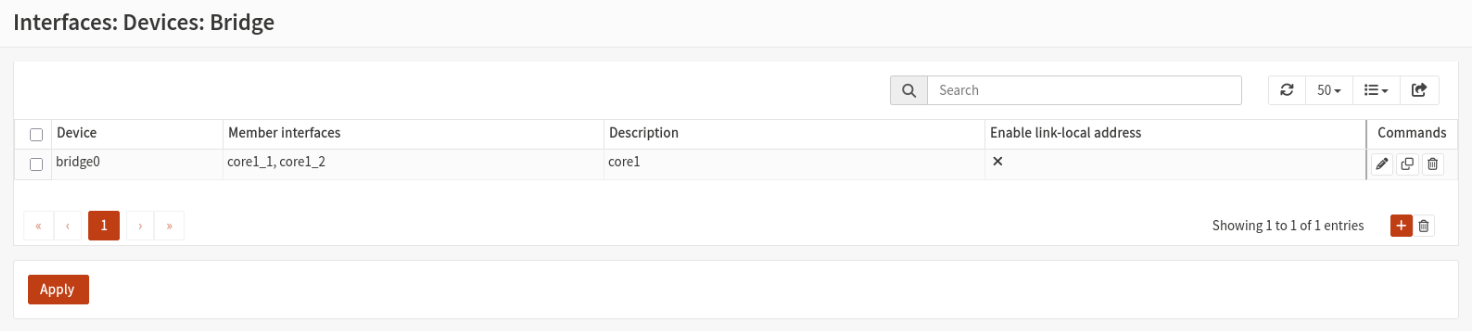
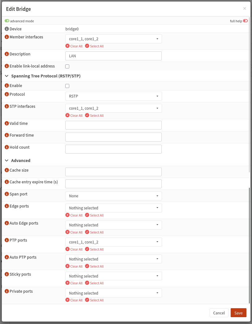
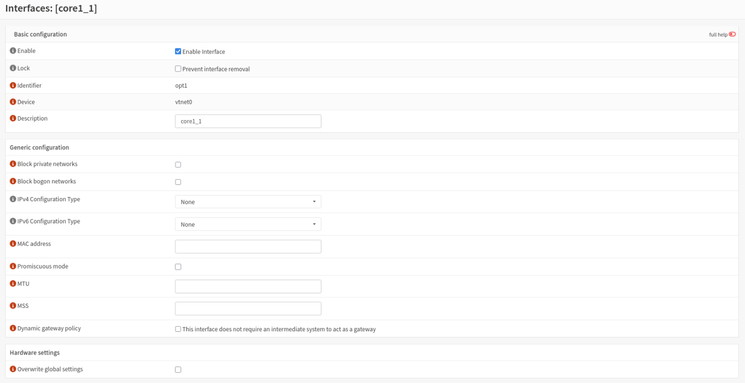
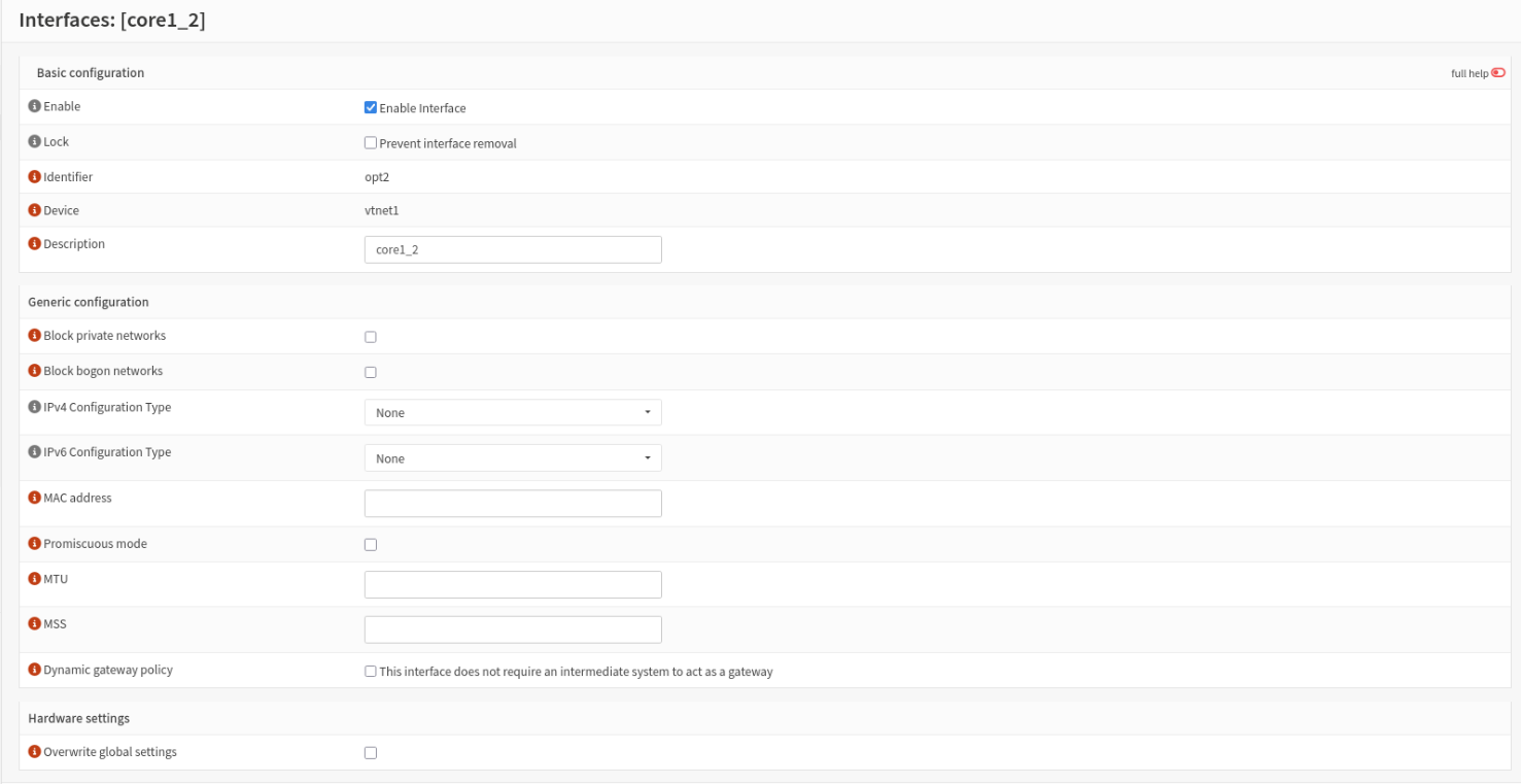
The LAN interfaces on each firewall are bridges with 2 members; 1 interface connects to sw-core1-1 and the other to sw-core1-2. This means that the network will continue to function as long as 1 router and 1 core switch remain online.
All bridges on the routers:
Bridge to Cores:
core1_1 (Bridge Member) Interface Configuration:
core1_2 (Bridge Member) Interface Configuration:
Firewall configuration (excluding floating rules):
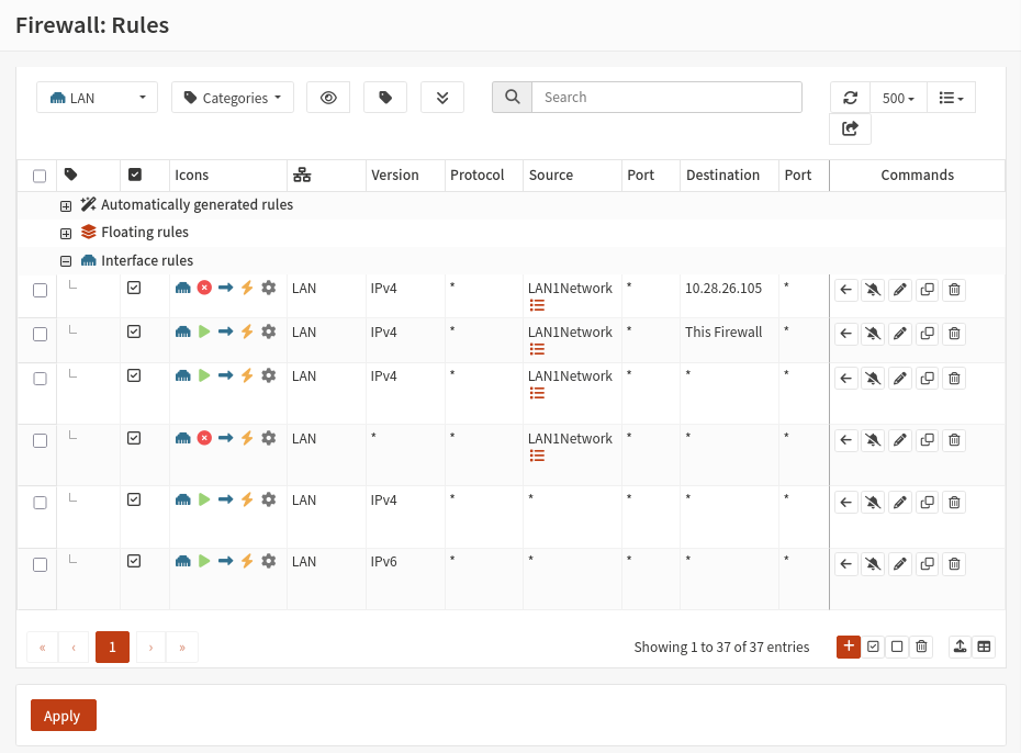
Note that there are rules here to force traffic from LAN1Network through GCP. This is because this network (LAN1 is a VLAN) is intended to use GCP as it's gateway via a site-to-site VPN instead of PureVPNDedicated1 or WAN. NAT rules are not used for this traffic as that is handled by the Fortigate on the other side of the VPN.
Gateways
The following gateways are configured on the firewalls. These gateways are used as the destinations in static routes and in some firewall rules (like the one mentioned above for LAN1Network):
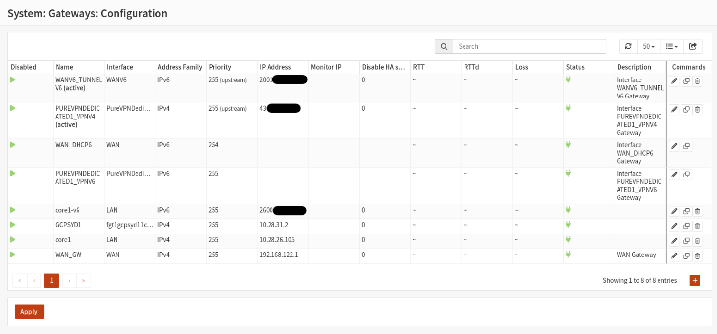
- PUREVPNDEDICATED1_VPN4 is used to route traffic to the Internet via PureVPN.
- core1 and core1-v6 is used to route internal traffic to the core switches.
- WAN_GW is used to route traffic to the Internet via the real WAN link (no VPN).
- WANV6_TUNNEL is used to route Internet traffic using IPv6 via the GIF tunnel to Hurricane Electric.
- GCPSYD1 is the remote IP of the Fortigate in an IPSec tunnel to reach gcpsyd1-1, gcpsyd1-2 and for LAN1: the Internet.
Static Routes
The following static routes are configured on the firewalls:
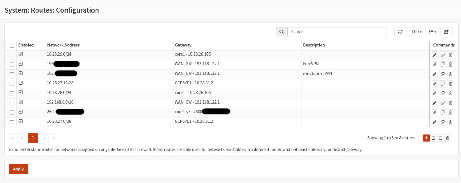
The following are the gateways and their associated static routes:
- core1
- 10.28.26.0/24 - The subnet on the core1 side of the next. These are the vast majority of internal addresses behind router1.This subnet is further divided into VLANs on core1.
- 10.28.29.0/24 - VLAN on the core1 side which is routed to the Internet via a Fortigate in GCP. The NAT for this traffic is handled on the Fortigate in GCP.
- WAN_GW (real WAN)
- 192.168.0.0/24 - My home network on the WAN side of router1. This resides outside GNS3.
- [REDACTED] (description is "PureVPN") - The IP of the OpenVPN gateway I connect to for PureVPN. A route is setup here to force this connection to occur on the real WAN instead of via another VPN.
- 103.[REDACTED] (description is "windtunnel VPN") - A VPN to the pfSense firewall on my colocated server. This ensures this VPN connection occurs over the real WAN link instead of a VPN.
- GCPSYD1
- 10.28.27.16/28 - port2 (LAN) network on fgt1 in GCPSYD1.
- 10.28.27.0/28 - port1 (WAN) network on fgt1 in GCPSYD1.
- core1-v6
- 2600[REDACTED]/48 - Same as 10.28.26.0/24 but for IPv6.
NAT Firewall Configuration
There are 2 outgoing NAT rules configured on these firewalls; one for the physical WAN and the other for PureVPN interface:
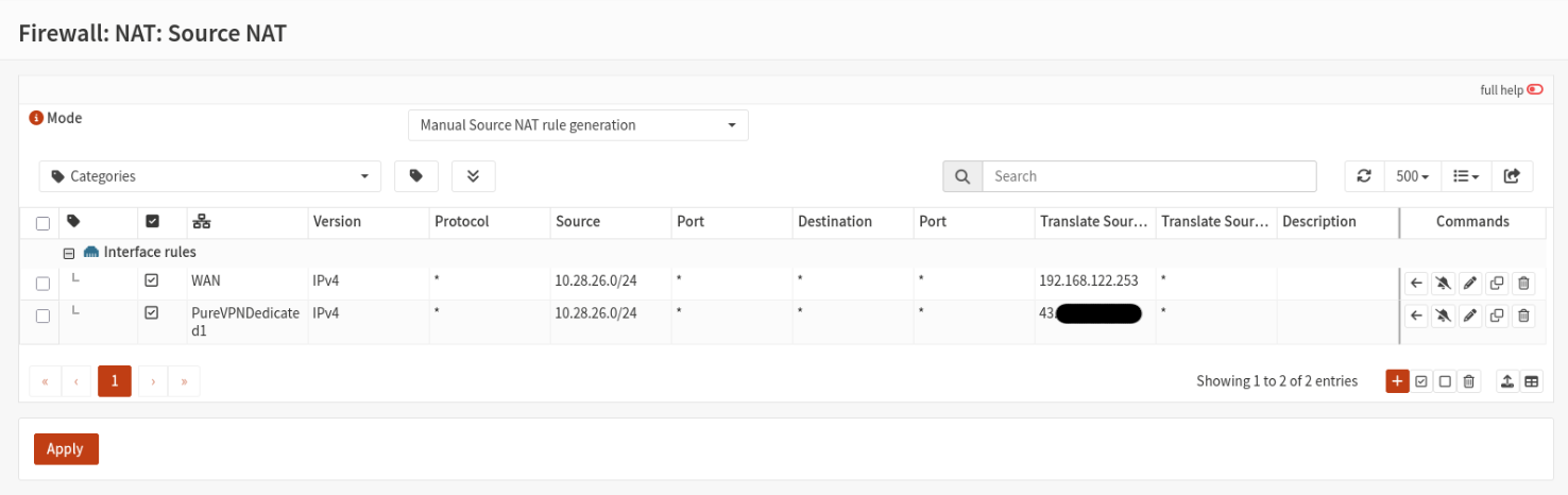
WAN configuration:
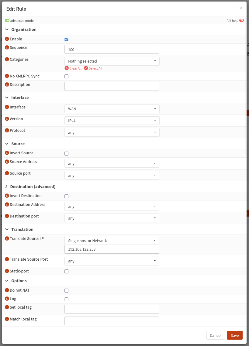
This causes any traffic from IPs behind the firewall leaving through the WAN interface are NAT'd to the WAN virtual IP address (192.168.122.253) of the firewall.
PureVPNDedicated1 configuration:
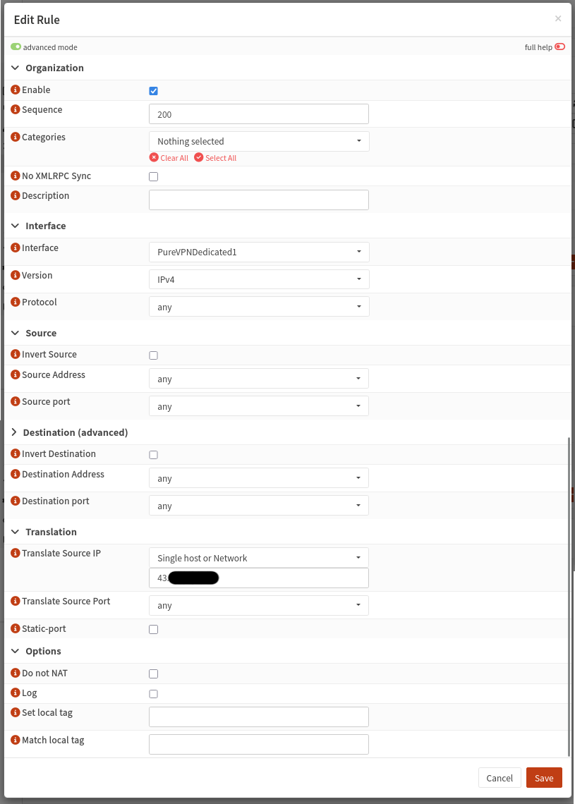
This causes any traffic from IPs behind the firewall leaving through the PureVPNDedicated1 interface are NAT'd to the PureVPNDedicated1 IP address of the firewall.
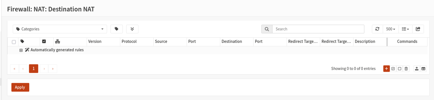
There are no port forwarding rules:
Floating Firewall Rules
Floating firewall rules apply to all interfaces unless specified in the rule itself. These are useful in cases where you want to broadly allow or disallow traffic, such as preventing multiple VLANs from accessing a specific IP without having to add that rule to each interface. Per-interface are applied after the floating rules provided the traffic is not fast-matched to a floating rule.
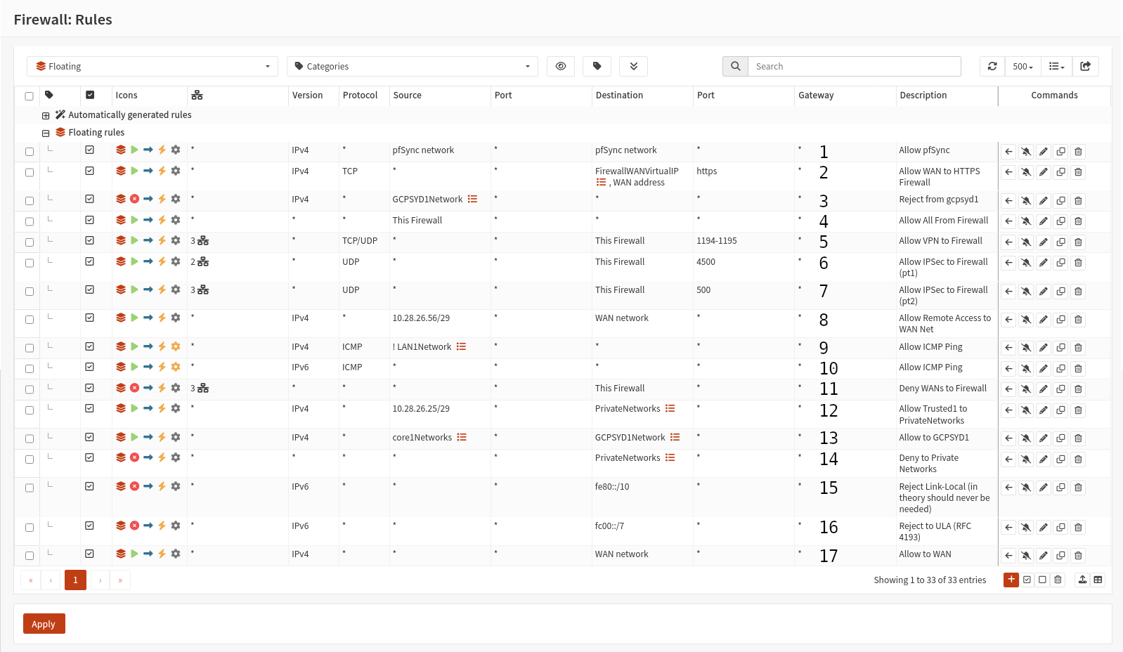
- Allow - IPv4 Any - Any - Allow all traffic from the pfSync network to itself (required for pfSync to work).
- Allow - IPv4 TCP - Any - Allow HTTPS traffic to the WAN (static and VIP) on the firewalls (for the web interface).
- Reject - IPv4 Any - Reject traffic from GCPSYD1Network to all.
- Allow - IPv4+6 Any - Allow all traffic from the routers themselves.
- Allow - IPv4+6 UDP - Src Int: PureVPNDedicated1,WAN,WANV6 - Allow ports 1194,1195 TCP and UDP to the firewall.
- Allow - IPv4+6 UDP - Src Int: PureVPNDedicated1,WANV6 - Allow 4500/udp to the firewall for IPSec NAT on the firewall. Required for the GCPSYD1 VPN.
- Allow - IPv4+6 UDP - Src Int: PureVPNDedicated1,WAN,WANV6 - Allow 500/udp to the firewall for IPSec on the firewall. Required for the windtunnel1 VPN.
- Allow - IPv4 Any - Src Int: Any - Allow Remote Access to WAN Net.
- Allow - IPv4 ICMP Echo Request - Src Int: Any - Allow ICMP pings from all addresses other than the LAN1 VLAN subnet.
- Allow - IPv6 ICMP Echo Request - Src Int: Any - Allow ICMP pings from all addresses.
- Deny - IPv4+6 Any - Src Int: PureVPNDedicated1,WAN,WANV6 - Reject all traffic from all WAN-type interfaces.
- Allow - IPv4 Any - Src Int: Any - Allow all traffic from the Trusted1 VLAN to 192.168.0.0/16, 10.0.0.0/8 and 172.16.0.0/12 and (if this rule wasn't IPv4-only) the /48 IPv6 range assigned to devices on the LAN side of the firewall. This is likely a defunct rule that carried over from the old pfSense configuration where traffic between VLANs went through the firewall.
- Allow - IPv4 Any - Src Int: Any - Allowed traffic from networks behind the cores (and remote access VPN) to GCPSYD1.
- Deny - IPv4+6 Any - Src Int: Any - Deny all traffic to 192.168.0.0/16, 10.0.0.0/8 and 172.16.0.0/12 and the /48 IPv6 range assigned to devices on the LAN side of the firewall.
- Deny - IPv6 Any - Src Int: Any - Deny all traffic from fe80::/10; the link-local network. Traffic SHOULD never hit this rule but it's there are a precaution.
- Deny - IPv6 Any - Src Int: Any - Deny all traffic from fc00::/7; the equivilent to IPv4 local IPs.
- Allow - IPv4 Any - Src Int: Any - Allow all traffic to the WAN interface's local subnet.
IPSec VPN Configurations
Overview:
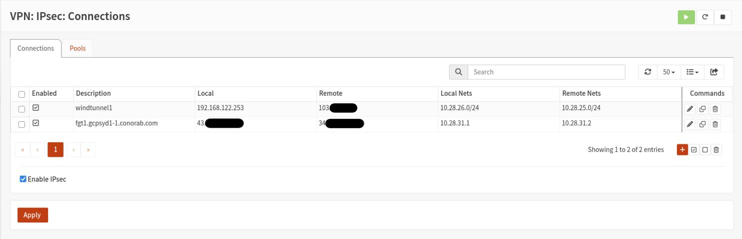
windtunnel1 VPN Configuration
digitaldoggo Side
IPSec Configuration
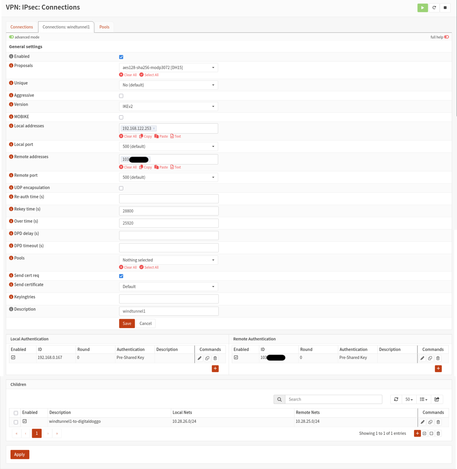
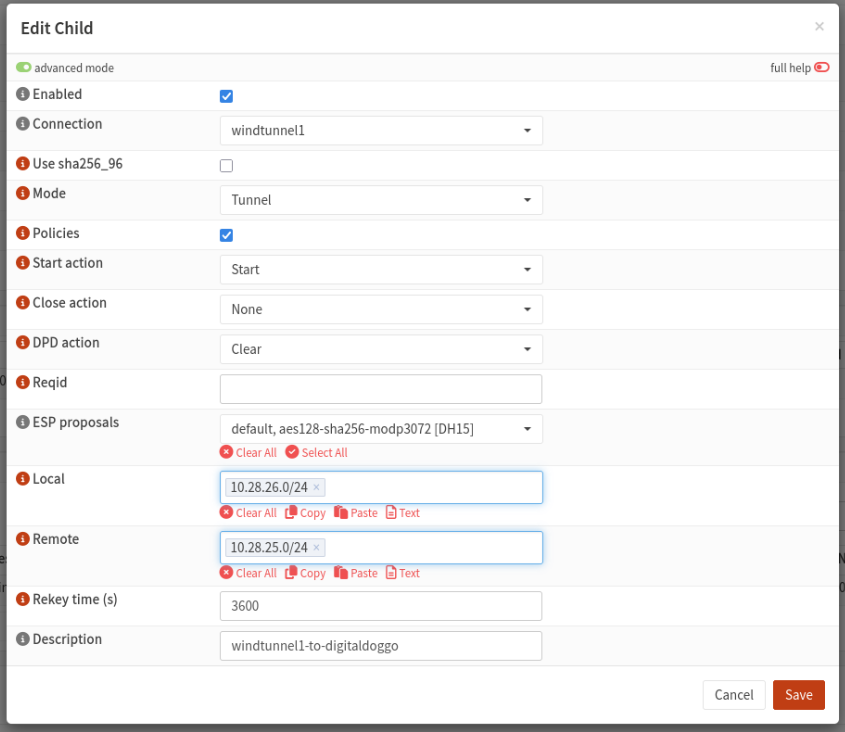
Firewall Rules
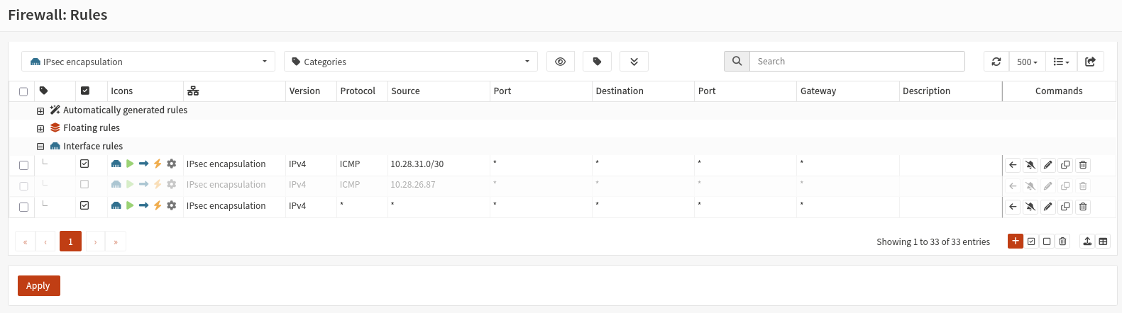
- Allow - IPv4 ICMP - Allow ICMP pings from 10.28.31.0/30 to all.
- Allow - IPv4 ICMP - Allow ICMP pings from 10.28.26.87 to all.
- Allow - IPv4 Any - Allow all.
windtunnel1 Side
IPSec Configuration
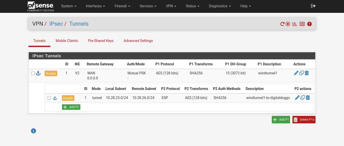
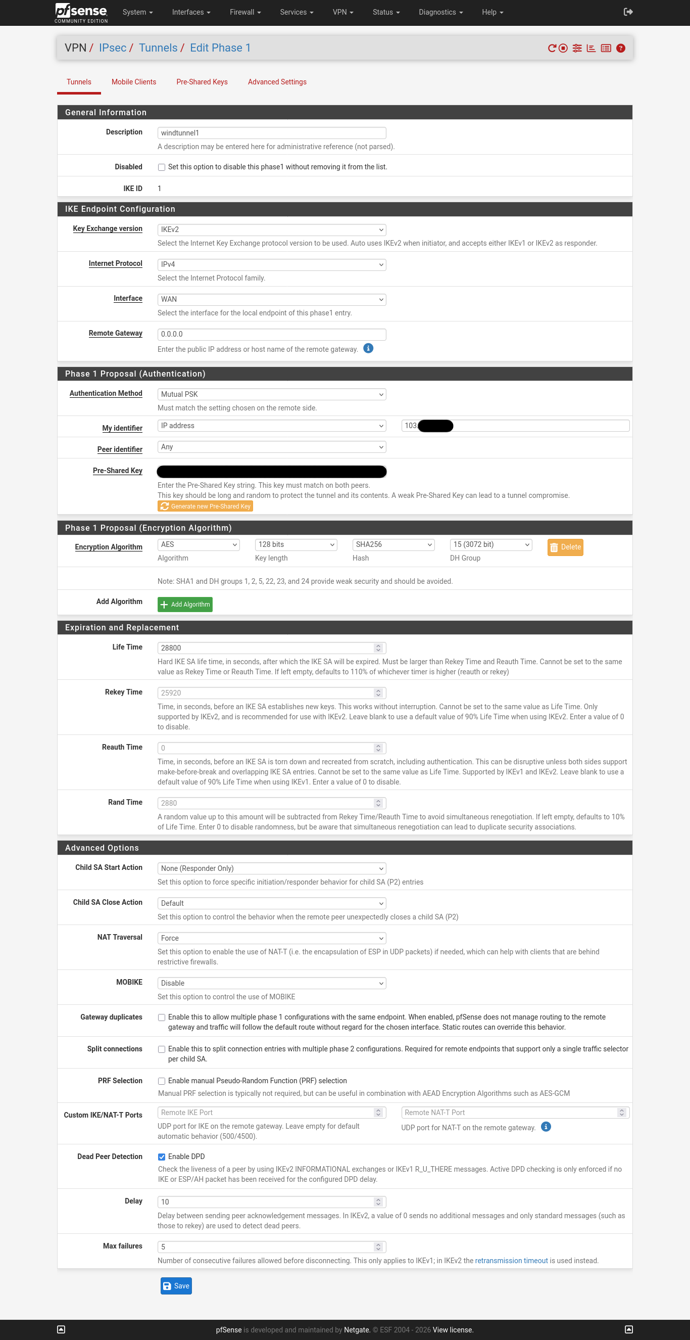
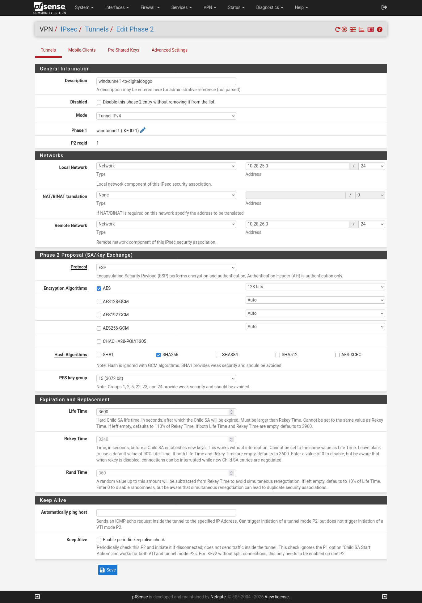
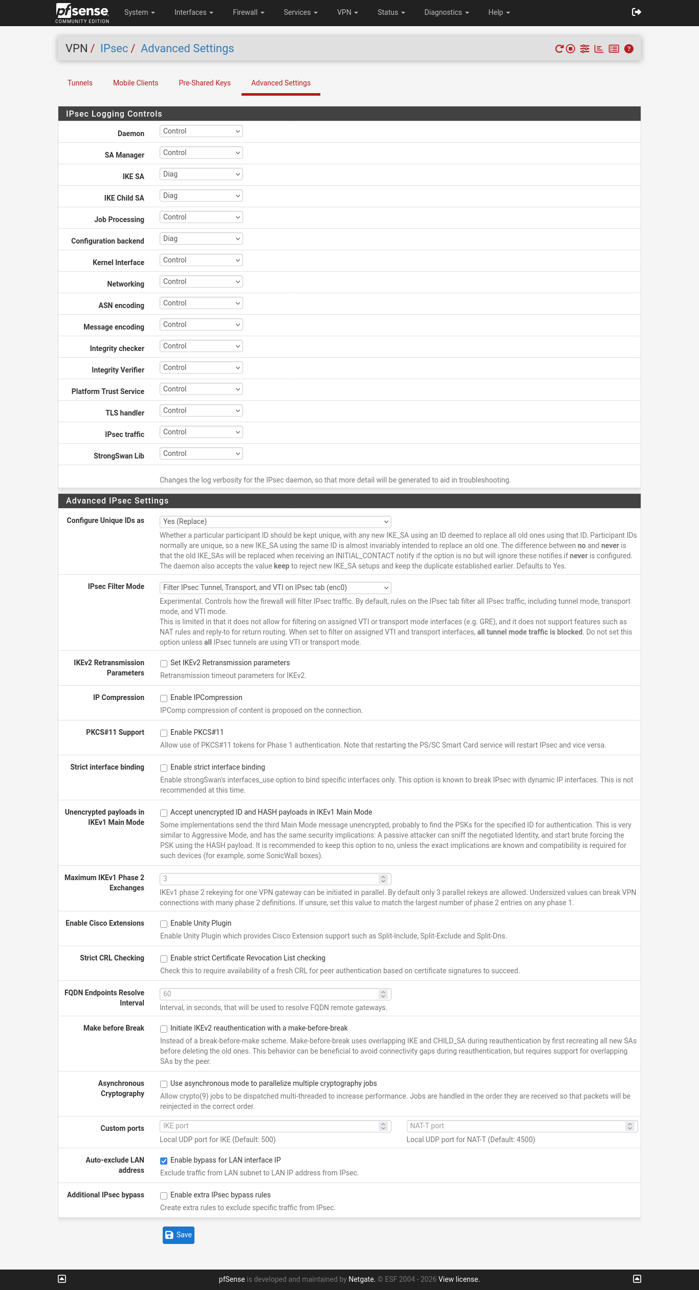
NAT Rules
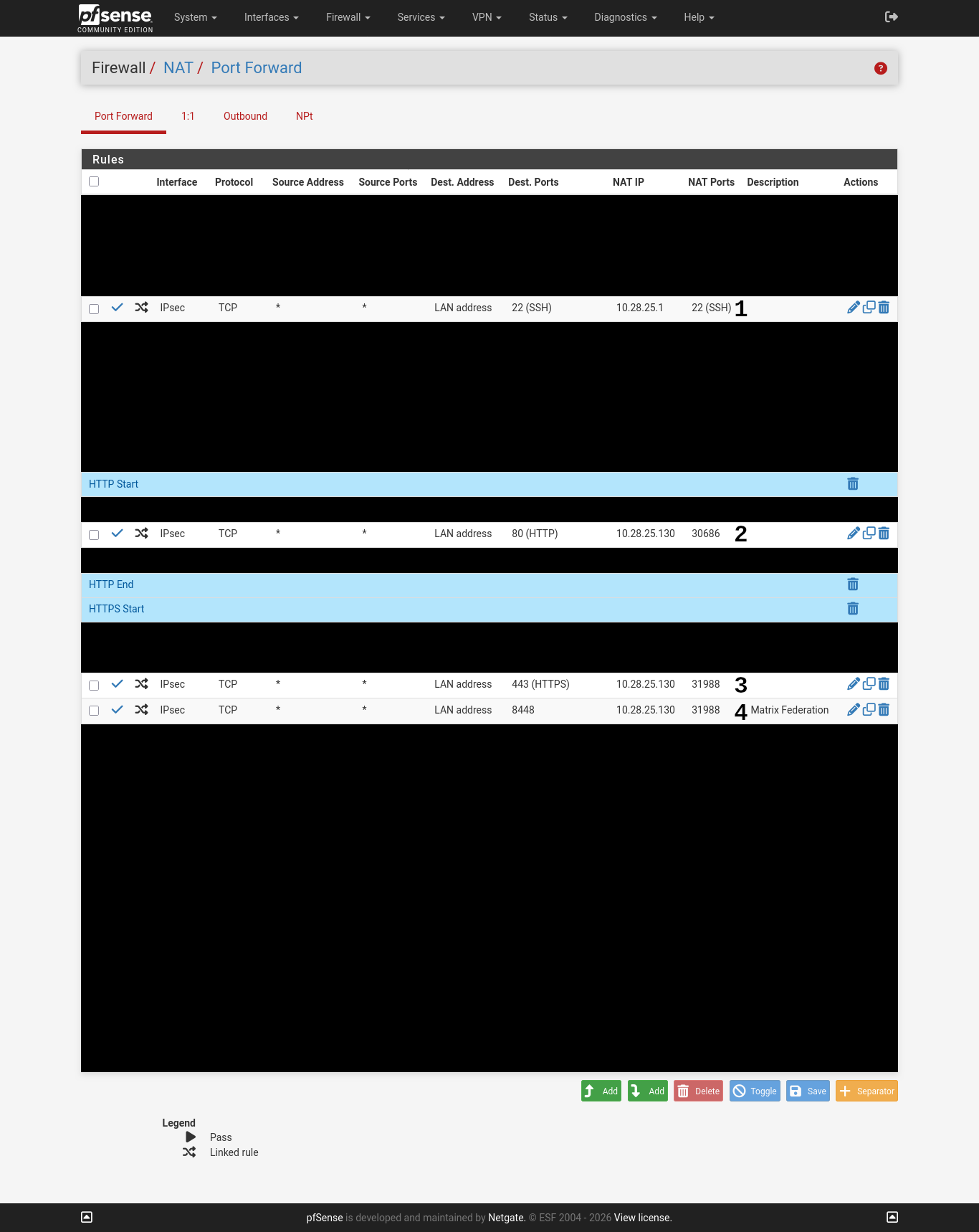
- Redirect port 22/tcp incoming on the LAN interface of the firewall to port 22/tcp on windtunnel1. This does not work as the corresponding firewall rule does not line up.
- Redirect port 80/tcp incoming on the LAN interface of the firewall to port 30686/tcp on kube1 (Kubernetes server) running an HTTP load balancer.
- Redirect port 443/tcp incoming on the LAN interface of the firewall to port 31988/tcp on kube1 (Kubernetes server) running an HTTPS load balancer.
- Redirect port 8448/tcp incoming on the LAN interface of the firewall to port 31988/tcp on kube1 (Kubernetes server) running an HTTPS load balancer.
Firewall Rules
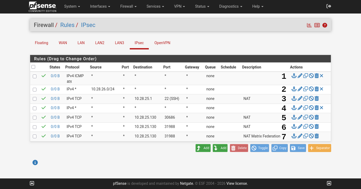
- Allow - IPv4 ICMP Any - Allow all ICMP pings.
- Allow - IPv4 Any - Allow all traffic from GNS3 lab.
- Allow - IPv4 TCP - Allow SSH traffic to windtunnel1. This is auto-created when the NAT rule was added. The rules now mismatch and so the rule is broken.
- Allow - IPv4 Any - Allow all traffic.
- Allow - IPv4 TCP - Allow HTTP traffic directed at the firewall's LAN IP to go to port 30686 on kube1 (Kubernetes server).
- Allow - IPv4 TCP - Allow HTTPS traffic directed at the firewall's LAN IP to go to port 31988 on kube1 (Kubernetes server).
- Allow - IPv4 TCP - Allow 8448/tcp traffic directed at the firewall's LAN IP to go to port 31988 on kube1 (Kubernetes server).
GCPSYD1 VPN Configuration
digitaldoggo Side
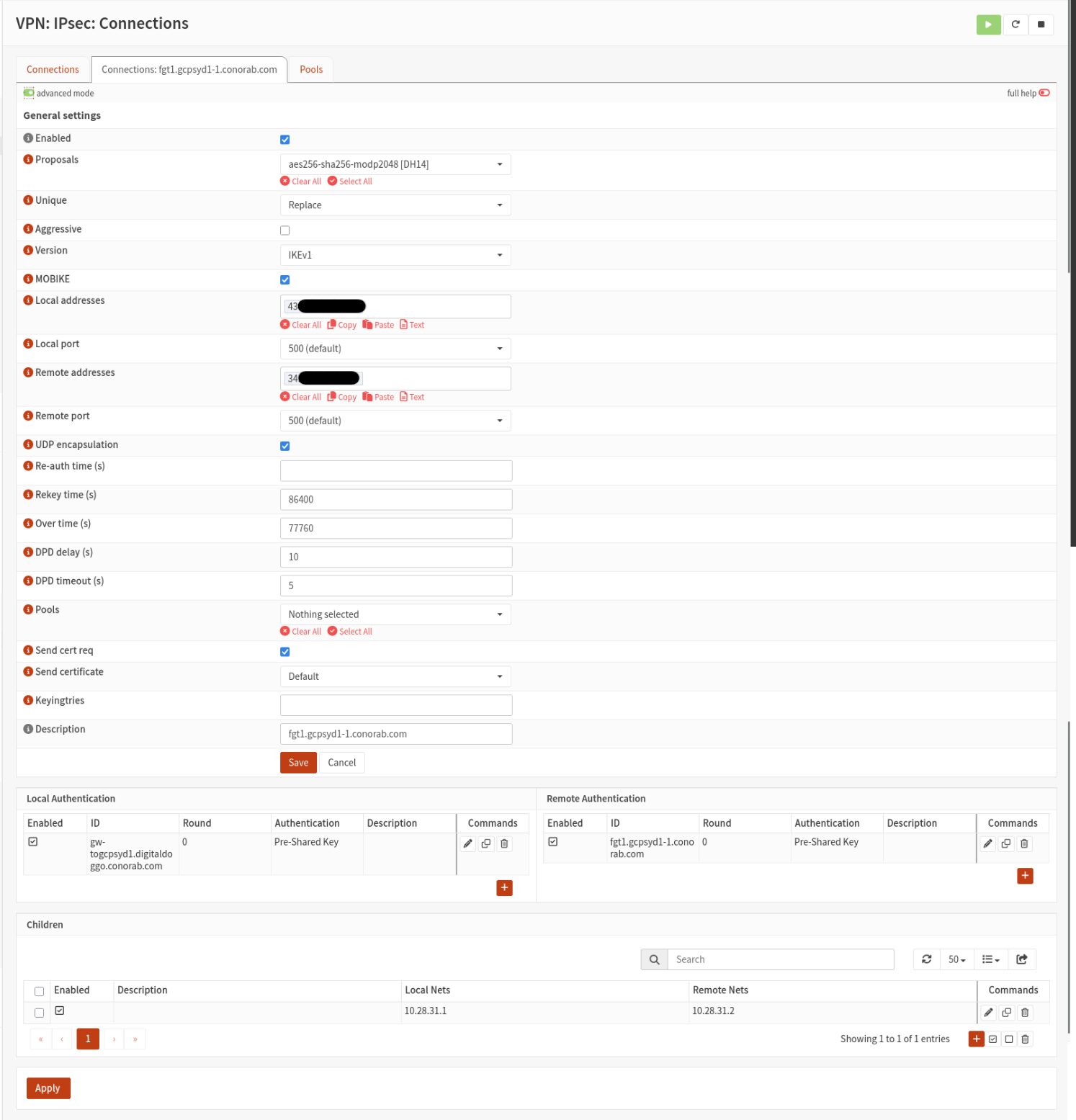
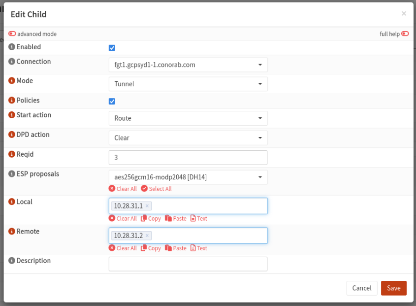
IPSec Configuration
Firewall Rules
fgt1 Configuration
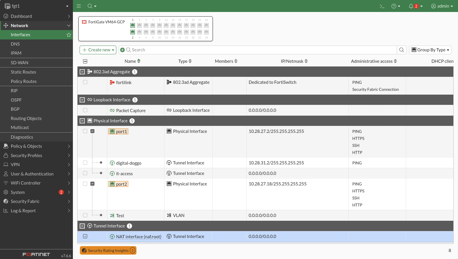
Interfaces
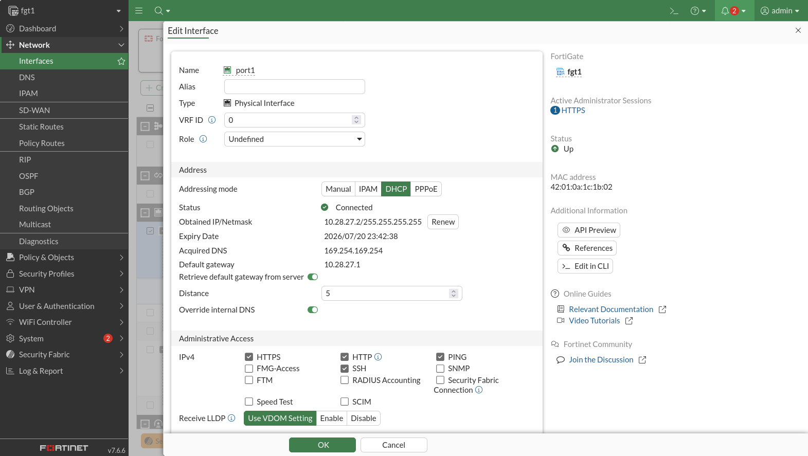
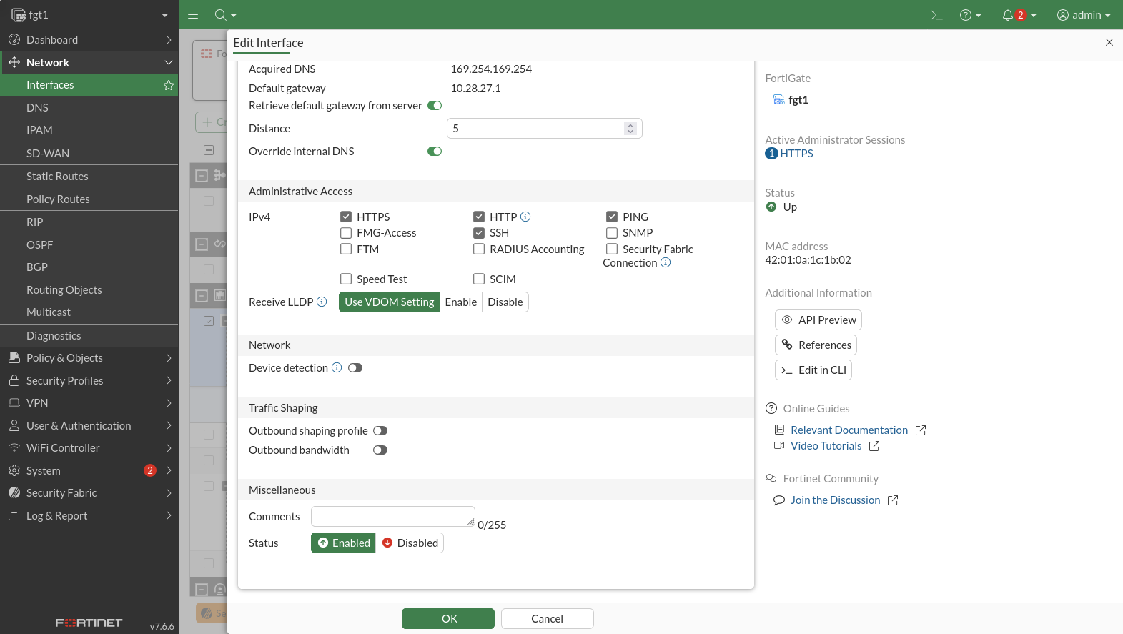
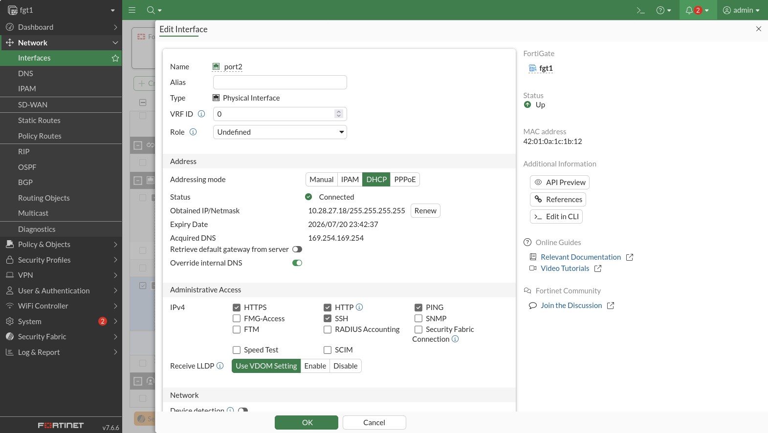
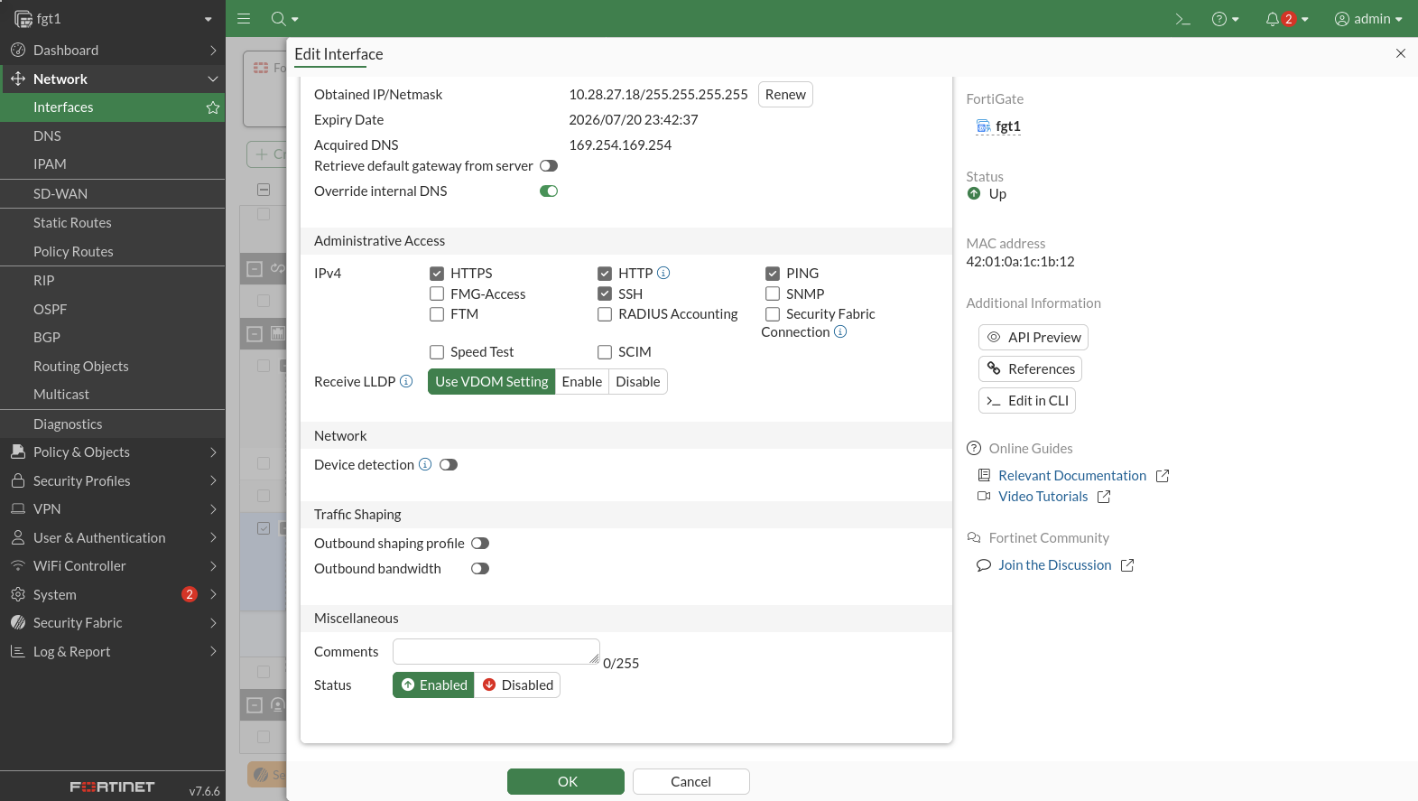
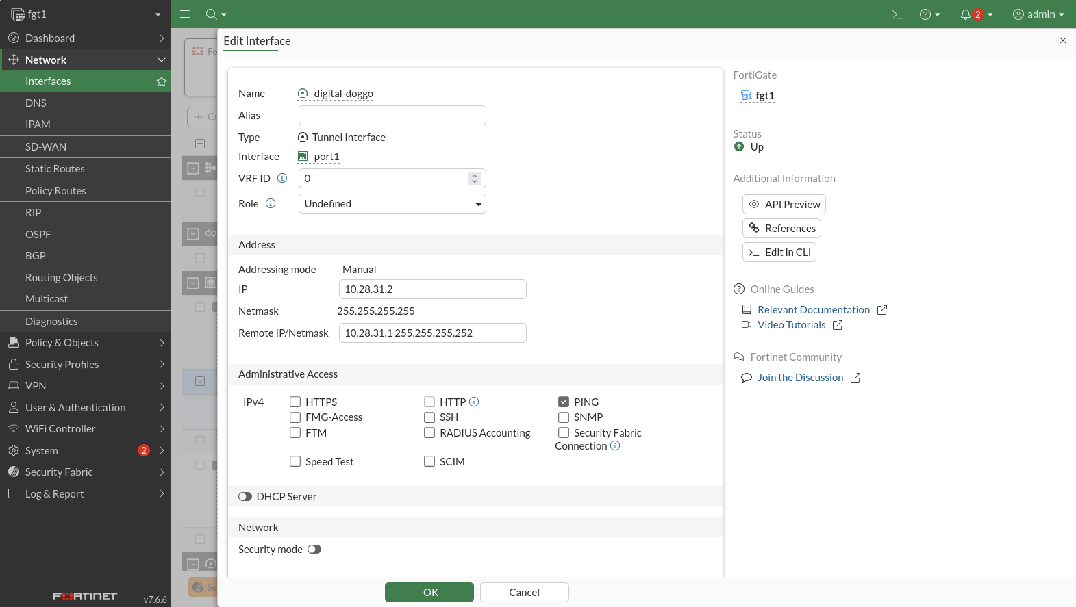
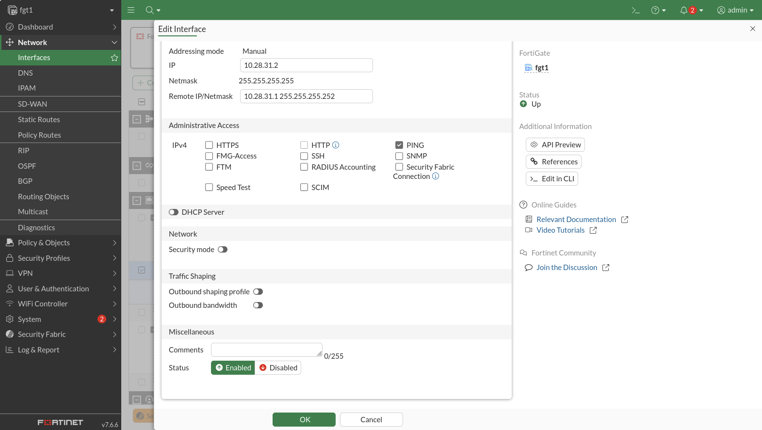
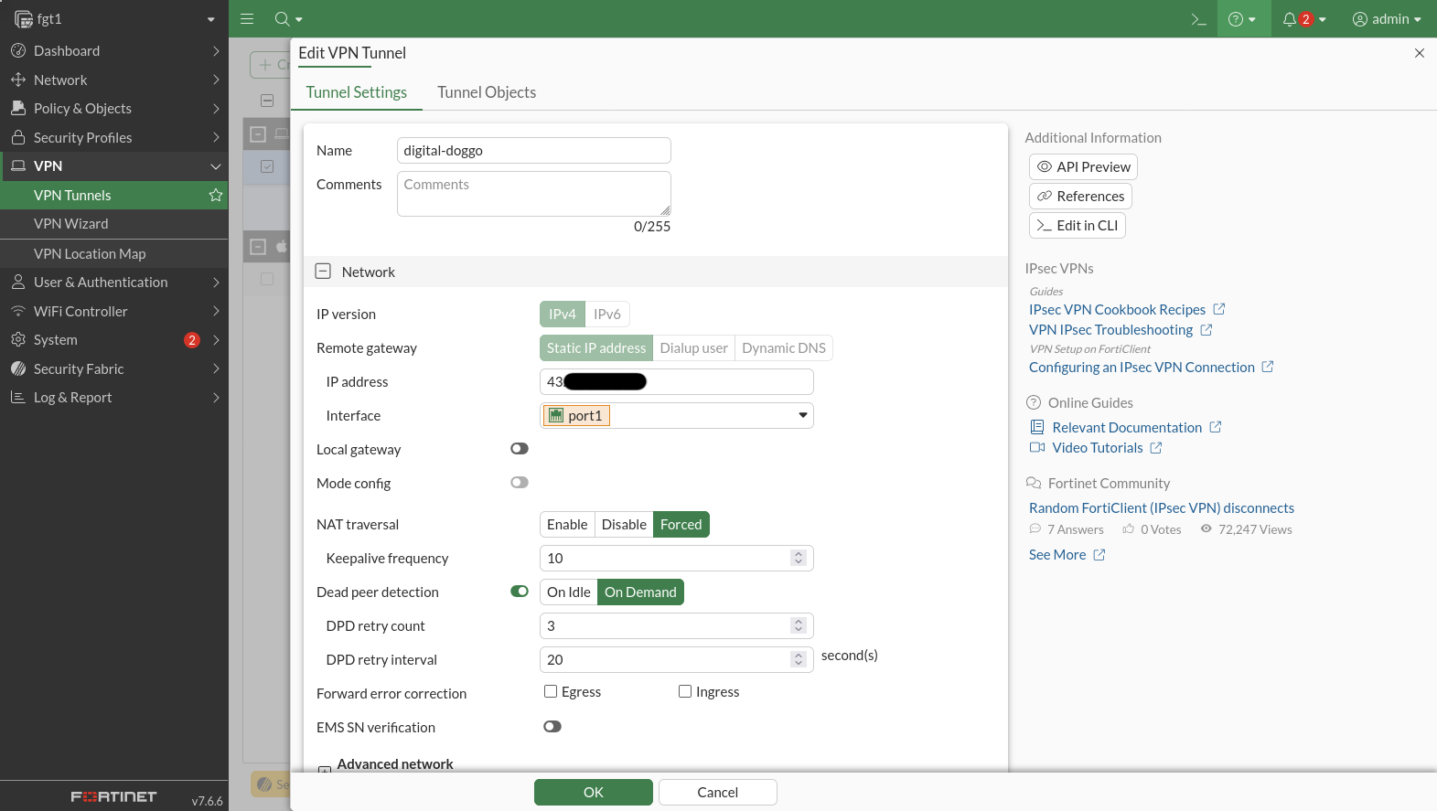
The WAN on fgt1 is port1, and the LAN is port 2. A seperate virtual inteface is created when you make an IPSec tunnel to the GNS3 Lab (digitaldoggo).
Static Routes
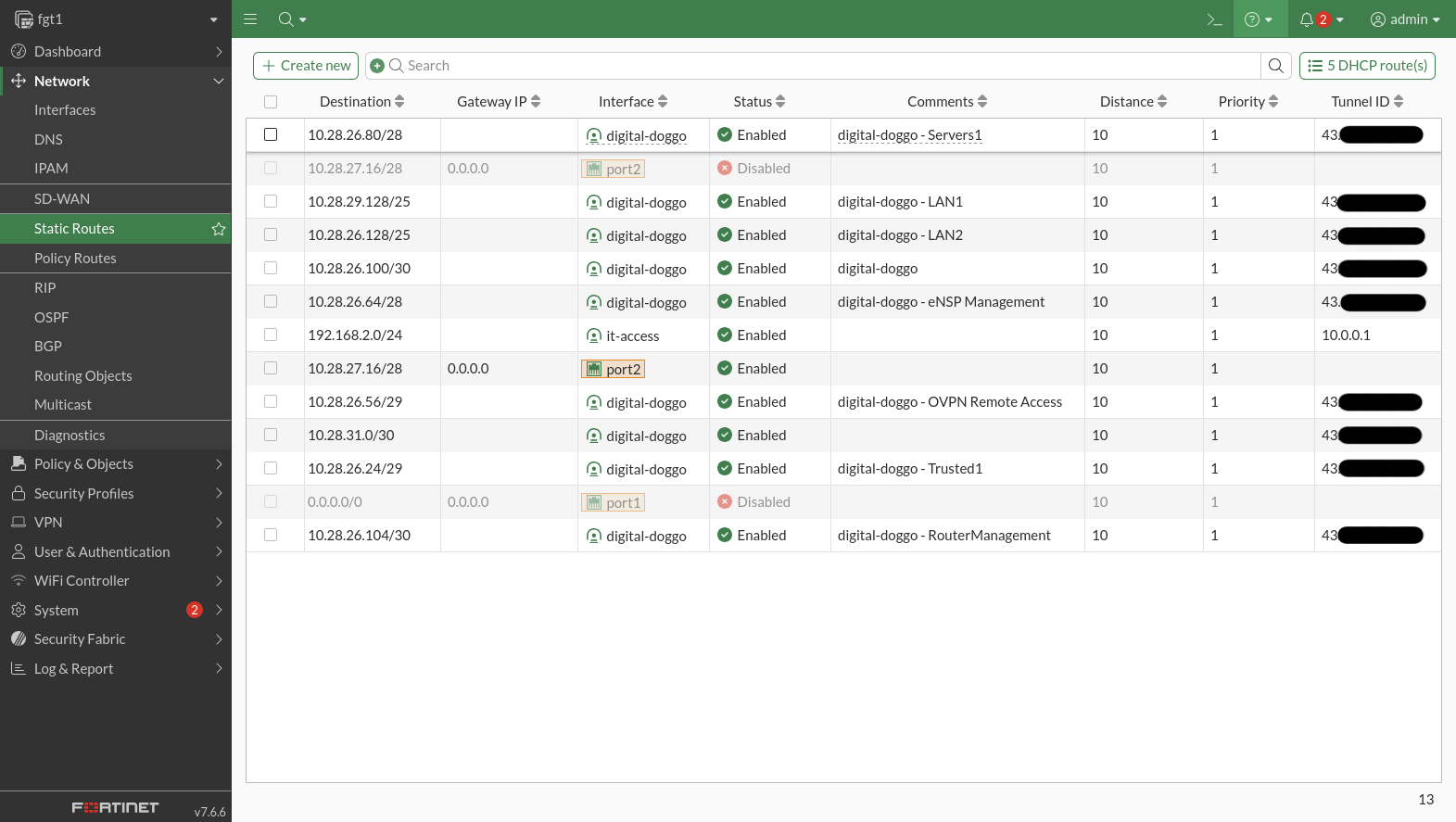
A static route is configured to point each subnet of the GNS3 Lab through the VPN.
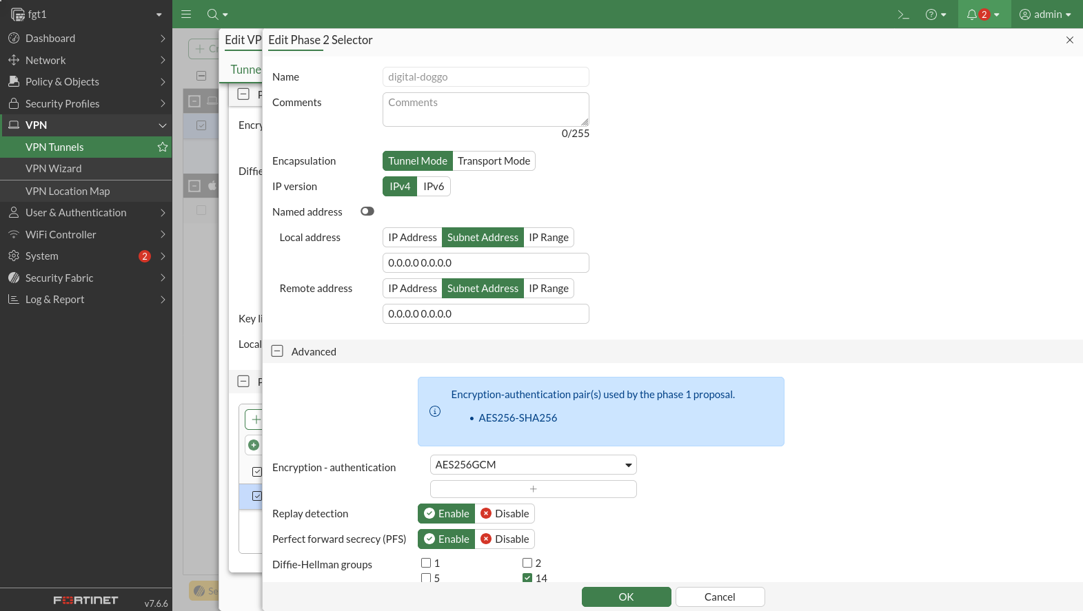
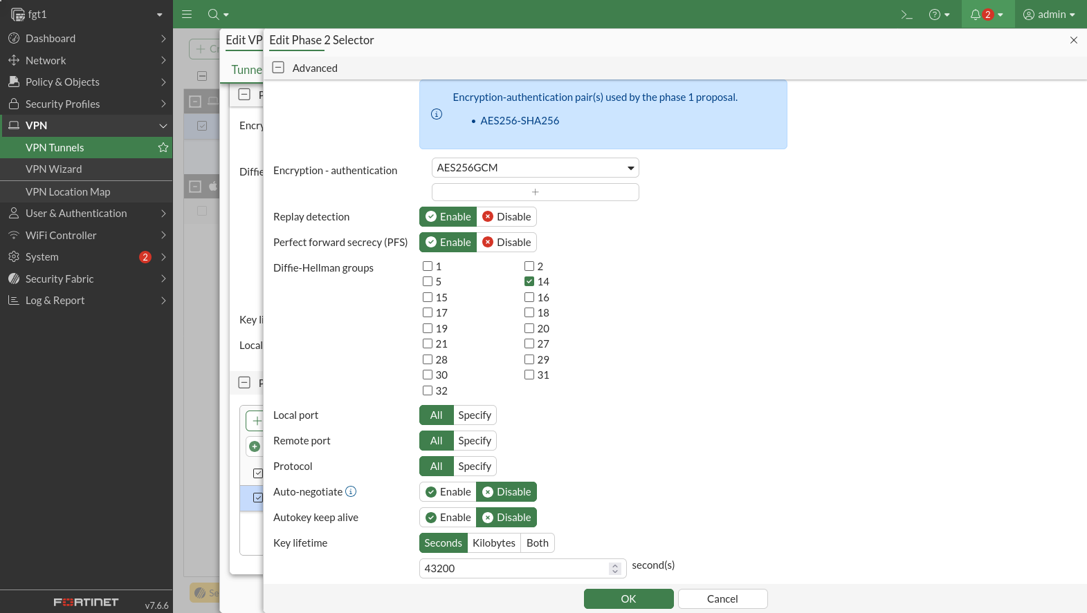
IPSec Configuration
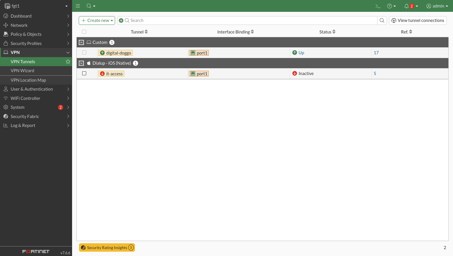
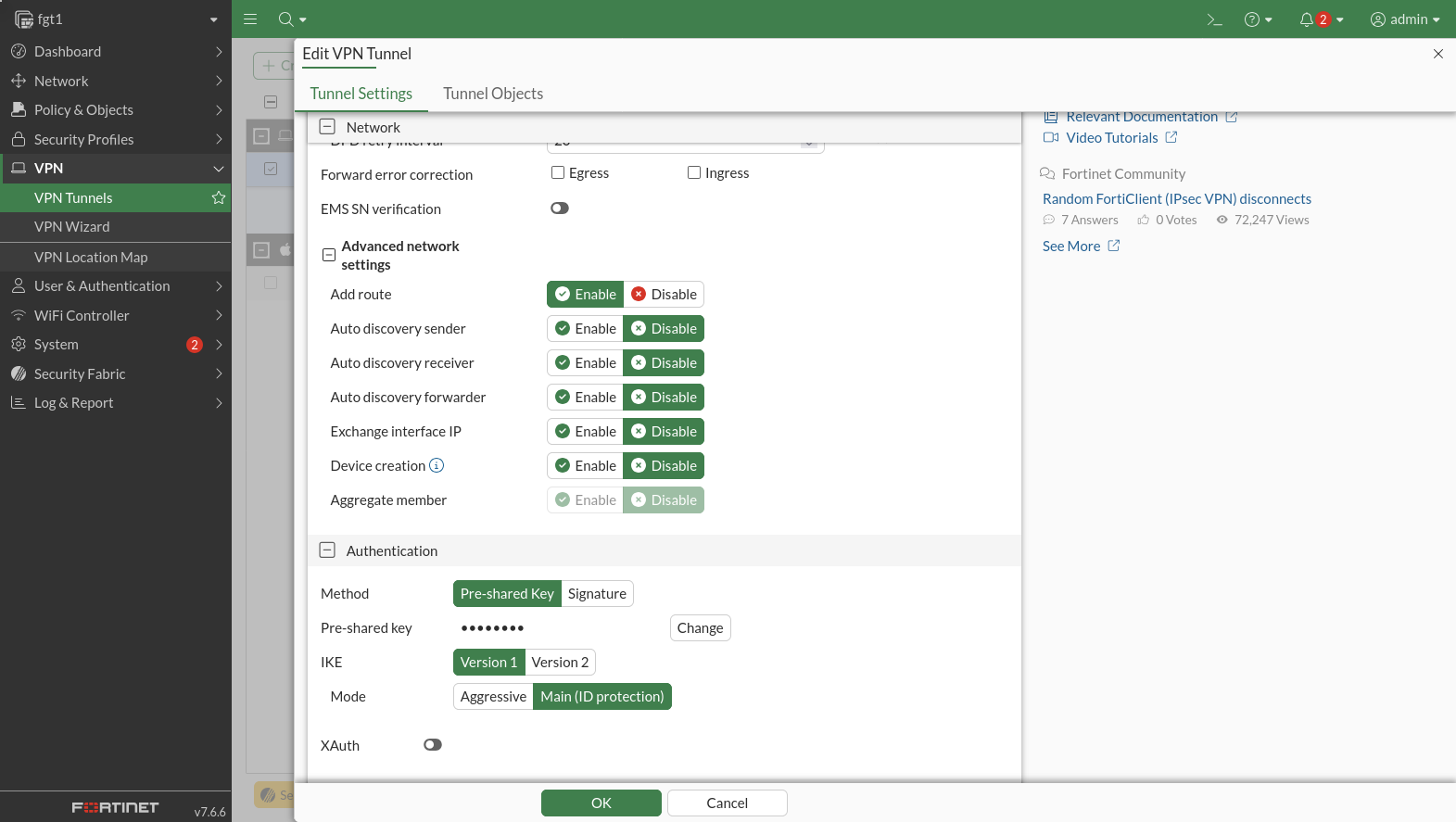
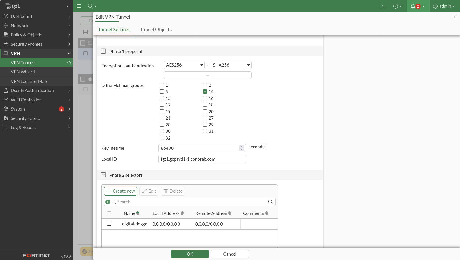
The IPSec site-to-site tunnel is configured under the digitaldoggo interface.
Firewall Rules
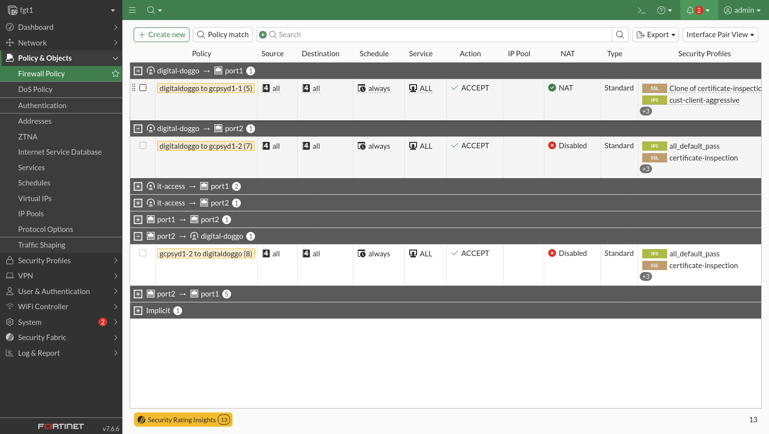
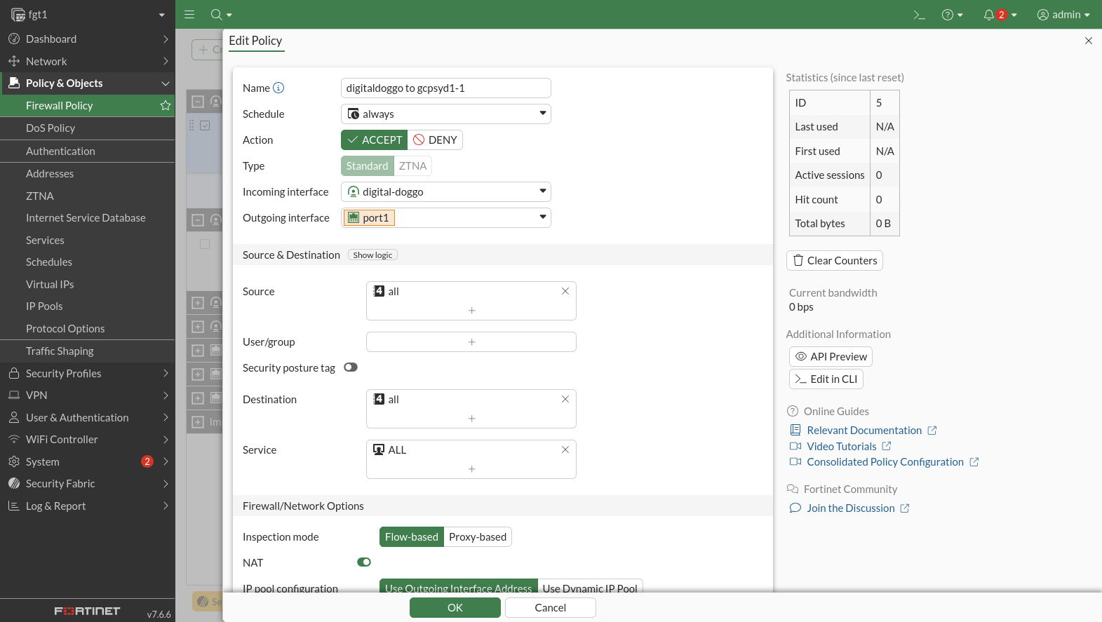
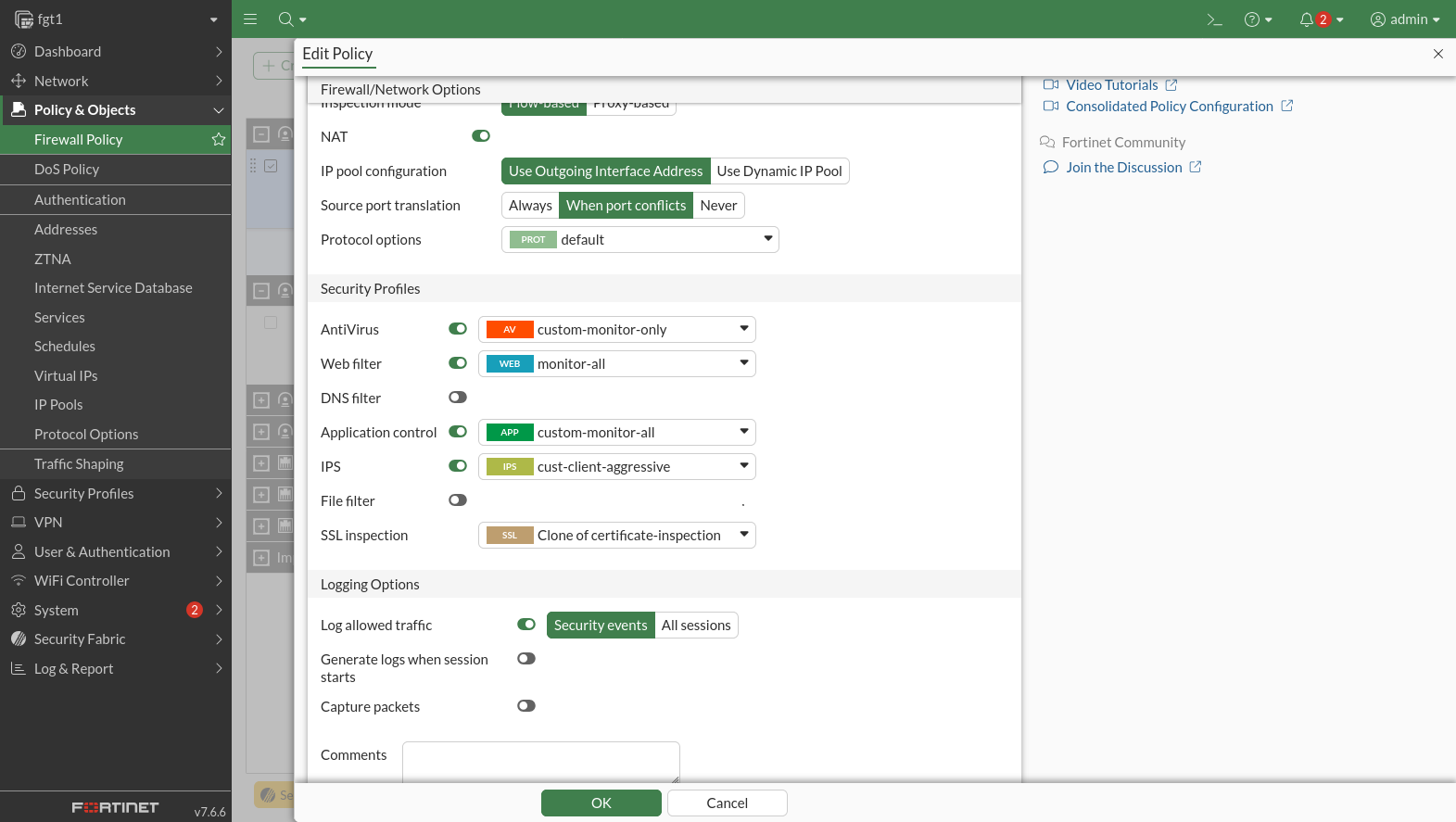
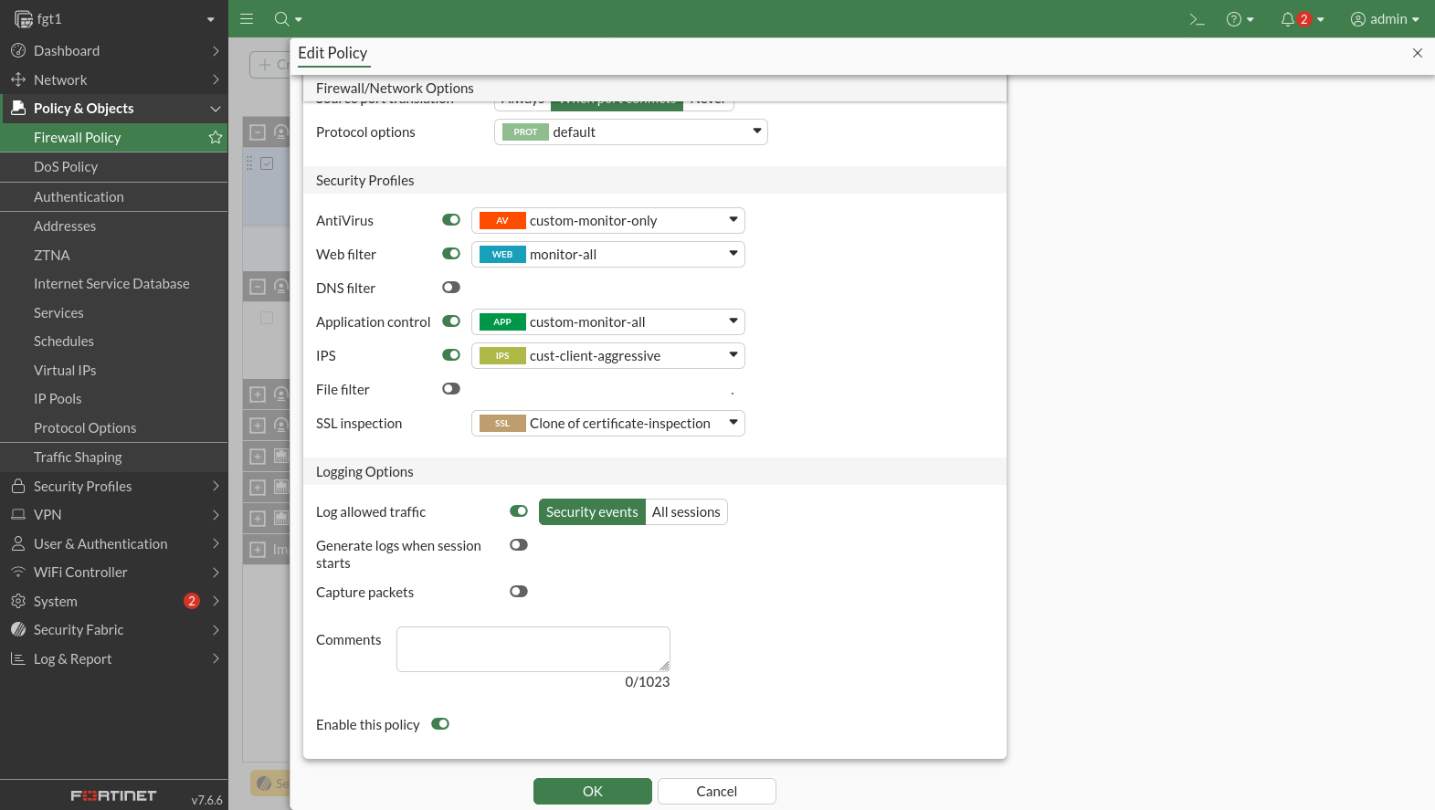
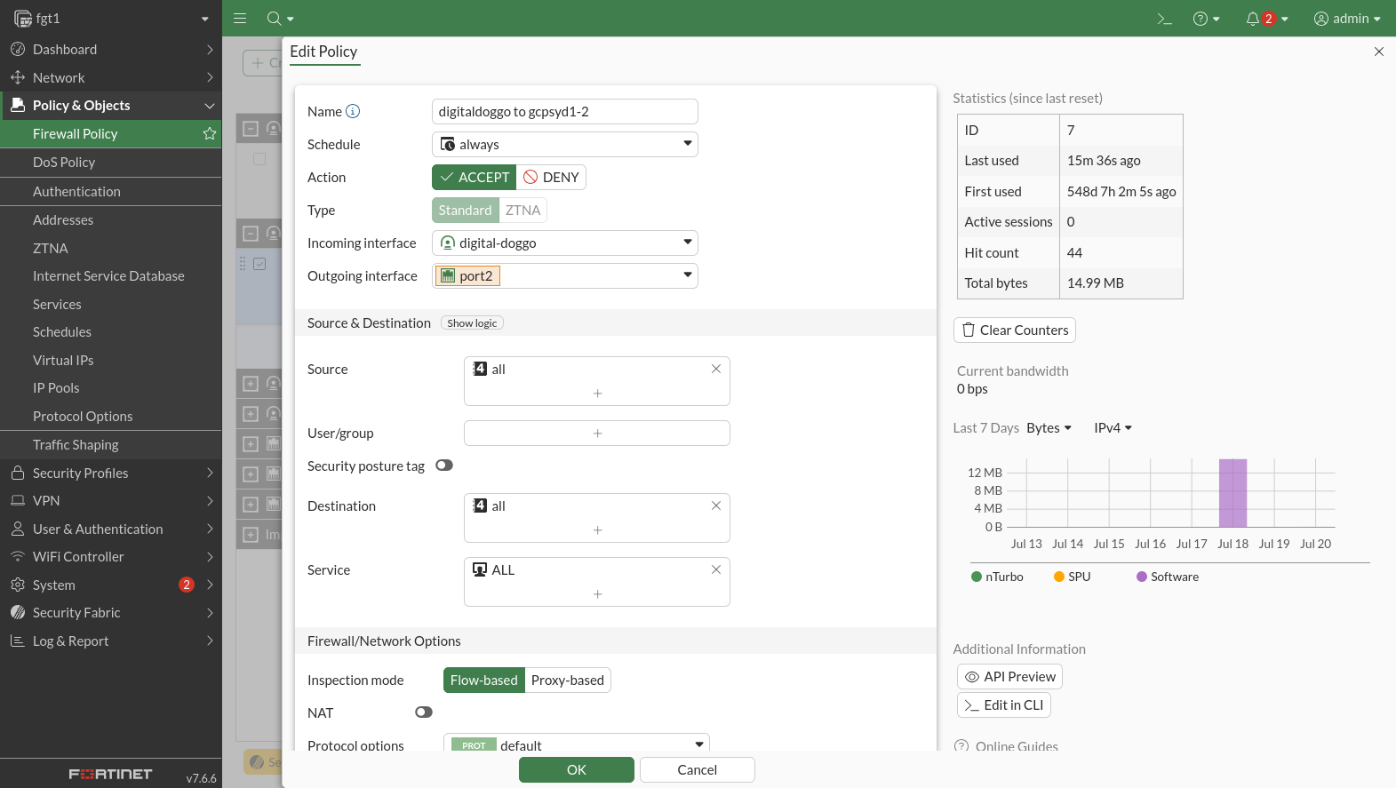
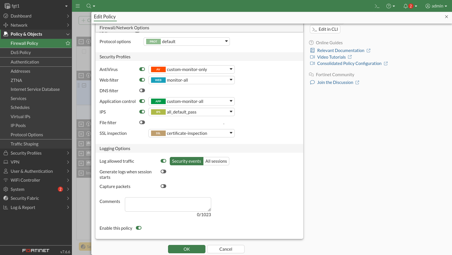
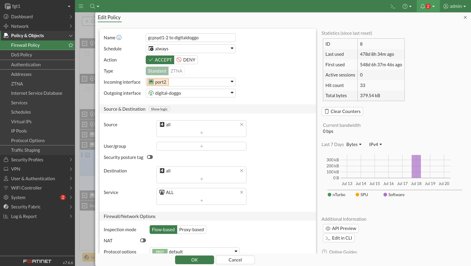
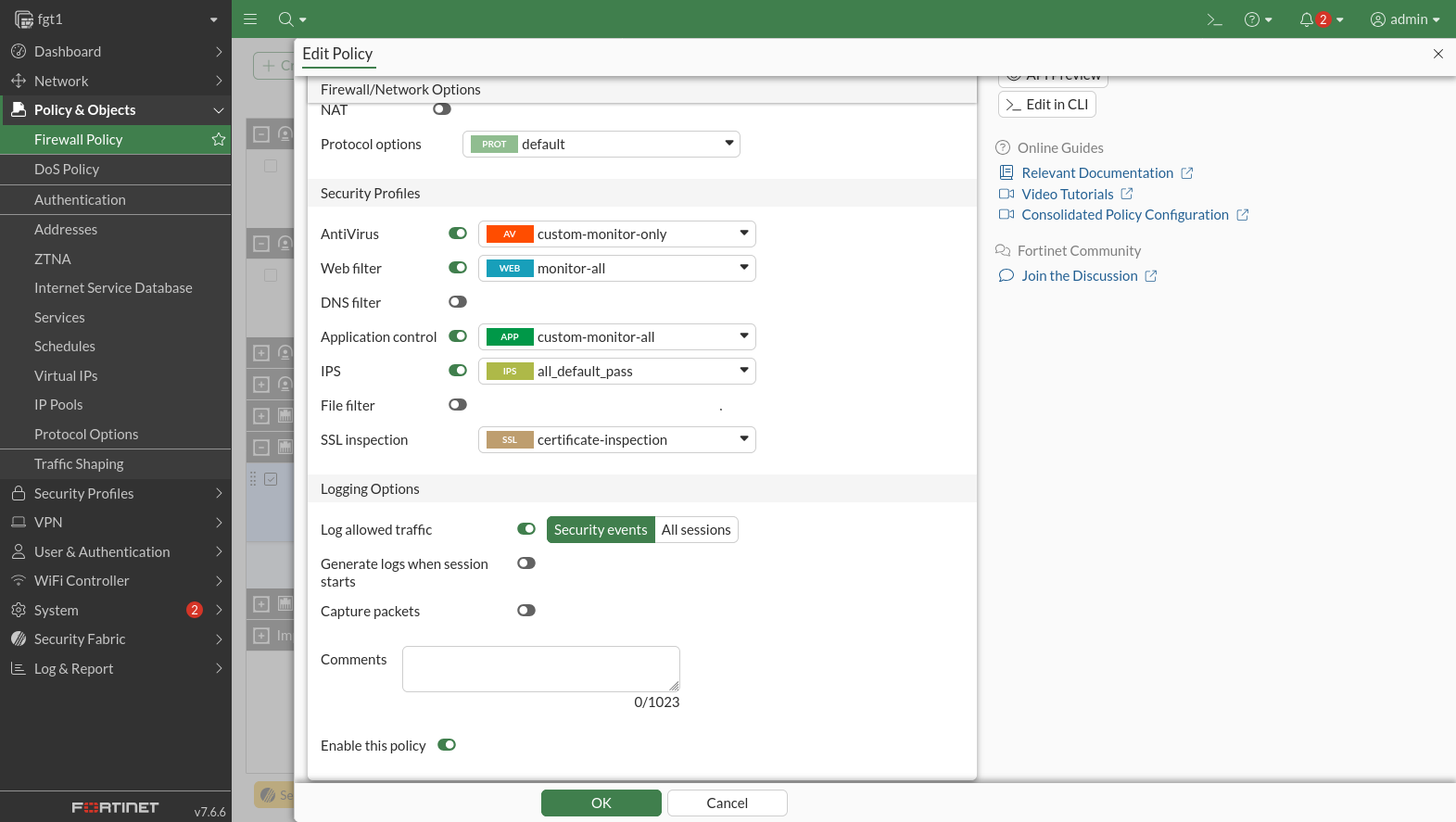
Firewall rules on the Fortigate are configured to allow traffic to mostly (minus the IPS configured on rule 5). NAT is applied to all traffic going through rule 5 so traffic from LAN1 on the GNS3 Lab can access the Internet via the Fortigate.
- (Rule 5) Allow - IPv4 Any - Allow all traffic from GNS3 Lab to WAN (port1) of fgt1 in GCPSYD1.
- (Rule 7) Allow - IPv4 Any - Allow all traffic from GNS3 Lab to LAN (port2) of fgt1 in GCPSYD1.
- (Rule 8) Allow - IPv4 Any - Allow all traffic from LAN (port2) of fgt1 in GCPSYD1 to GNS3 Lab.
Switch Configuration
ACL: AllButTrusted.pol
The AllButTrusted.pol ACL is applied to all VLANs except for Trusted1. This does the following in order and the first rule that matches is what is applied:
- Allow - IPv4 Any - Allow traffic from Trusted1.
- Allow - IPv4 Any - Allow IPv4 traffic to and from windtunnel1 over the VPN.
- Allow - IPv4 Any - Allow traffic from Remote Access VPN.
- Allow - IPv4 Any - Allow traffic to and from the Fortigate/GCP network over the VPN.
- Allow - IPv4 Any - Allow traffic from the LAN2 VLAN to the Servers1 VLAN.
- Allow - IPv4+6 ICMP - Allow ICMP traffic.
- Allow - IPv4 port 67-68 - Allow DHCP traffic.
- Allow - IPv4+6 Any - Allow VRRP traffic.
- Allow - IPv6 ICMP - Allow IPv6 neighbour solicitations and advertisements.
- Allow - IPv6 ICMPV6 - Allow traffic required for IPv6 router advertisements to work.
- Allow - IPv4+6 TCP - Allow traffic to the web interface (ports 80,443/tcp of the firewall.
- Allow - IPv4+6 UDP+TCP - Allow DNS traffic (53 UDP and TCP) to the DNS server on the firewall.
- Deny - IPv6 Any - Broken rule - In practice, deny all traffic from the Servers1 VLAN to itself. The intention appears to be to block IPv6 traffic for 2600:[REDACTED]::/48 rather than 2600:[REDACTED]::/64.
- Deny - IPv4+6 Any - Deny all traffic to local subnets on IPv4.
These rules are in place of rules that used to exist in pfSense and were moved onto the core switches when doing the migration to the GNS3 Lab. This was largely done out of interest and largely does work, but there are 1-2 major caveats to using these ACLs: they're not stateful rules, so you need to write ACLs that work in both directions of traffic and not just the side that started the session. This means that in practice you are allowing networks you'd otherwise like to block to retain access on a limited sets of ports. This is why the block rules are setup to allow the blocked side to communicate on ports 32768-65535. These are ephemeral ports that Linux and Windows use on the client side when connecting to another computer and are usually left closed unless there is an active connection. However, this does mean that the blocked network will be able to speak to a device on another network if that device is listening on an ephemeral port, which does happen. This is a major reason why it is beneficial to use a firewall to route between networks instead of a switch: switch ACLs are usually stateless. This said, stateless ACLs are still perfectly reasonable in some circumstances, like when you want to completely block one VLAN from another in both directions.
entry allowFromTrusted1-replyTcp {
  if {destination-address 10.28.26.25/29; protocol 6; source-port 1-1024; destination-port 32768-65535;}
  then {permit;}
}

entry allowFromTrusted1-replyUdp {
  if {destination-address 10.28.26.25/29; protocol 17; source-port 1-1024; destination-port 32768-65535;}
  then {permit;}
}

entry allowFromTrusted1-replyRDP {
  if {destination-address 10.28.26.25/29; protocol 6; source-port 3389; destination-port 32768-65535;}
  then {permit;}
}

entry allowFromTrusted1-v6-replyTcp {
  if {destination-address 2600[REDACTED]:6::/64; protocol 6; source-port 1-1024; destination-port 32768-65535;}
  then {permit;}
}

entry allowFromTrusted1-v6-replyUdp {
  if {destination-address 2600[REDACTED]:6::/64; protocol 17; source-port 1-1024; destination-port 32768-65535;}
  then {permit;}
}

entry allowFromTrusted1-v6-replyRDP {
  if {destination-address 2600[REDACTED]:6::/64; protocol 6; source-port 3389; destination-port 32768-65535;}
  then {permit;}
}

entry allowToWindtunnel-source {
  if {source-address 10.28.25.0/24;}
  then {permit;}
}

entry allowToWindtunnel-dest {
  if {destination-address 10.28.25.0/24;}
  then {permit;}
}

entry allowFromVPN-replyAny {
  if {source-address 10.28.26.56/29;}
  then {permit;}
}

entry allowFromVPN-dest {
  if {destination-address 10.28.26.56/29;}
  then {permit;}
}

entry allowFromVPN-v6-replyAny {
  if {source-address 2600[REDACTED]:2::/64;}
  then {permit;}
}

entry allowFromVPN-v6-dest {
  if {destination-address 2600[REDACTED]:2::/64;}
  then {permit;}
}

entry allowToGCPSYD1-replyAll {
  if {source-address 10.28.27.0/27}
  then {permit;}
}

entry allowToGCPSYD1-dest {
  if {destination-address 10.28.27.0/27;}
  then {permit;}
}

entry allowLAN2ToServers1-replyTcp {
  if {source-address 10.28.26.128/25; destination-address 10.28.26.80/28; protocol 6; source-port 1-1024; destination-port 32768-65535;}
  then {permit;}
}

entry allowLAN2ToServers1-replyUdp {
  if {source-address 10.28.26.128/25; destination-address 10.28.26.80/28; protocol 17; source-port 1-1024; destination-port 32768-65535;}
  then {permit;}
}

entry allowLAN2ToServers1 {
  if {source-address 10.28.26.80/28; destination-address 10.28.26.128/25;}
  then {permit;}
}

entry allowLAN2ToServers1-v6-replyTcp {
  if {source-address 2600[REDACTED]::/64; destination-address 2600[REDACTED]:1::/64; protocol 6; source-port 1-1024; destination-port 32768-65535;}
  then {permit;}
}

entry allowLAN2ToServers1-v6-replyUdp {
  if {source-address 2600[REDACTED]::/64; destination-address 2600[REDACTED]:1::/64; protocol 17; source-port 1-1024; destination-port 32768-65535;}
  then {permit;}
}

entry allowLAN2ToServers1-v6 {
  if {source-address 2600[REDACTED]:1::/64; destination-address 2600[REDACTED]::/64;}
  then {permit;}
}

entry allowICMP-reply {
  if {protocol 1; ICMP-Type 0;}
  then {permit;}
}

entry allowICMP-request {
  if {protocol 1; ICMP-Type 8;}
  then {permit;}
}

entry allowICMPv6-reply {
    if { protocol icmpv6; icmp-type 129; }
    then { permit; }
}

entry allowICMPv6-request {
    if { protocol icmpv6; icmp-type 128; }
    then { permit; }
}

entry allowDHCP {
  if {protocol 17; source-port 67-68; destination-port 67-68;}
  then {permit;}
}

entry allowVRRP3 {
    if {protocol 112;}
    then {permit;}
}

entry allowICMPV6_NeighborSol {
    if {protocol icmpv6; icmp-type 135;}
    then {permit;}
}

entry allowICMPV6_NeighborAdv {
    if {protocol icmpv6; icmp-type 136;}
    then {permit;}
}

entry allowRA-client {
  if { protocol icmpv6; icmp-type 133;}
  then {permit;}
}

entry allowRA-Switch1 {
  if {protocol icmpv6; icmp-type 134; ethernet-source-address 00:00:5e:00:01:67 mask ff:ff:ff:ff:ff:ff;}
  then {permit;}
}

entry allowRA-Servers1 {
  if {protocol icmpv6; icmp-type 134; ethernet-source-address 00:00:5e:00:01:66 mask ff:ff:ff:ff:ff:ff;}
  then {permit;}
}

entry allowRA-LAN2 {
  if {protocol icmpv6; icmp-type 134; ethernet-source-address 00:00:5e:00:01:64 mask ff:ff:ff:ff:ff:ff;}
  then {permit;}
}

entry allowToFirewall-dest {
  if {destination-address 10.28.26.104/29; protocol 6; destination-port 443;}
  then {permit;}
}

entry allowToFirewall-replyTcp {
  if {source-address 10.28.26.104/29; protocol 6; source-port 443; destination-port 32768-65535;}
  then {permit;}
}

entry allowFirewall-replyHTTPS-v6 {
  if {destination-address 2600[REDACTED]:3::1/128; protocol 6; destination-port 443;}
  then {permit;}
}

entry allowFirewall-dest-v6 {
  if {source-address 2600[REDACTED]:3::1/128; protocol 6; source-port 443;}
  then {permit;}
}

entry allowToFirewallD-destDNSUDP {
  if {destination-address 10.28.26.104/29; protocol 17; destination-port 53;}
  then {permit;}
}

entry allowToFirewall-replyDNSUDP {
  if {source-address 10.28.26.104/29; protocol 17; source-port 53; destination-port 32768-65535;}
  then {permit;}
}

entry allowFirewall-destDNSUDP-v6 {
  if {source-address 2600[REDACTED]:3::1/128; protocol 17; source-port 53;}
  then {permit;}
}

entry allowFirewall-replyDNSUDP-v6 {
  if {destination-address 2600[REDACTED]:3::1/128; protocol 17; destination-port 53;}
  then {permit;}
}

entry allowToFirewallD-destDNSTCP {
  if {destination-address 10.28.26.104/29; protocol 6; destination-port 53;}
  then {permit;}
}

entry allowToFirewall-replyDNSTCP {
  if {source-address 10.28.26.104/29; protocol 6; source-port 53; destination-port 32768-65535;}
  then {permit;}
}

entry allowFirewall-destDNSTCP-v6 {
  if {source-address 2600[REDACTED]:3::1/128; protocol 6; source-port 53;}
  then {permit;}
}

entry allowFirewall-replyDNSTCP-v6 {
  if {destination-address 2600[REDACTED]:3::1/128; protocol 6; destination-port 53;}
  then {permit;}
}

entry denyV6LAN {
  if {source-address 2600[REDACTED]::/48; destination-address 2600[REDACTED]::/48;}
  then {deny;}
}

entry denyAToA {
  if {source-address 10.0.0.0/8; destination-address 10.0.0.0/8;}
  then {deny;}
}

entry denyAToC {
  if {source-address 10.0.0.0/8; destination-address 192.168.0.0/16;}
  then {deny;}
}

entry denyAToB {
  if {source-address 10.0.0.0/8; destination-address 172.16.0.0/12;}
  then {deny;}
}

entry denyCToA {
  if {source-address 192.168.0.0/16; destination-address 10.0.0.0/8;}
  then {deny;}
}

entry denyCToC {
  if {source-address 192.168.0.0/16; destination-address 192.168.0.0/16;}
  then {deny;}
}

entry denyCToB {
  if {source-address 192.168.0.0/16; destination-address 172.16.0.0/12;}
  then {deny;}
}

entry denyBToA {
  if {source-address 172.16.0.0/12; destination-address 10.0.0.0/8;}
  then {deny;}
}

entry denyBToC {
  if {source-address 172.16.0.0/12; destination-address 192.168.0.0/16;}
  then {deny;}
}

entry denyBToB {
  if {source-address 172.16.0.0/12; destination-address 172.16.0.0/12;}
  then {deny;}
}
sw-core1-1
- sw-core1-1 is the primary switch and is what traffic usually routes through behind the firewall.
- sw-core1-2 is the secondary which takes over if sw-core1-1 goes offline.
- The configuration of both switches is conceptually the same but differs in the switch IPs and ports.
VLANs
VLANs are configured as follows. Only the RouterManagement VLAN is shown below as an example:
create vlan "RouterManagement"
configure vlan RouterManagement tag 10
configure vlan RouterManagement add ports 3-4 untagged
configure vlan RouterManagement ipaddress 10.28.26.105 255.255.255.248
enable ipforwarding vlan RouterManagement
configure vlan RouterManagement ipaddress eui64 fe80::/64
configure vlan RouterManagement ipaddress 2600:[REDACTED]:3::3/64
- Name: RouterManagement
- VLAN ID: 10
- Untagged ports: 3-4
- IPv4 Address: 10.28.26.105 255.255.255.248
- IP Routing: Yes
- IPv6 address 1: eui64 fe80::/64
- IPv6 Address 2: 2600:[REDACTED]:3::3/64
LACP Configuration
LACP is configured as shown below. Configuration applied to the first port in the group is applied to the group as a whole:
enable sharing 5 grouping 5-6 lacp
enable sharing 1 grouping 1-2 lacp
enable sharing 7 grouping 7-8 lacp
Routing
The cores act as the routes for all devices across VLANs. However, the cores still need a default route so devices can reach the Internet:
configure iproute add default 10.28.26.107
configure iproute add default 2600:[REDACTED]:3::1
DHCP Relay
You can configure the switch to act as a DHCP relay instead of having your DHCP server sit on each VLAN. In this case, the VIP of the routers is the DHCP server and the switch is configured to relay DHCP traffic on the LAN1, LAN2 and Trusted1 VLANs to the routers.
enable dhcp vlan Mgmt
configure bootprelay add 10.28.26.107 vr VR-Default
enable bootprelay ipv4 vr VR-Default
configure bootprelay vlan LAN1 add 10.28.26.107
configure bootprelay vlan LAN2 add 10.28.26.107
configure bootprelay vlan Trusted1 add 10.28.26.107
Spanning Tree
The switches are configured to use spanning tree to prevent loops. Enable spanning tree and device the region ID:
configure mstp region 0ca24f810000
configure stpd s0 priority 4096
Automatically enable spanning tree on any ports on the following VLANs:
enable stpd s0 auto-bind vlan DMZ
enable stpd s0 auto-bind vlan eNSPManagement
enable stpd s0 auto-bind vlan LAN1
enable stpd s0 auto-bind vlan LAN2
enable stpd s0 auto-bind vlan RouterManagement
enable stpd s0 auto-bind vlan Servers1
enable stpd s0 auto-bind vlan Switch1
enable stpd s0 auto-bind vlan NetworkSimulator
enable stpd s0 auto-bind vlan Trusted1
Configure ports 1, 3, 4, 5 and 7 as switch ports:
configure stpd s0 ports link-type point-to-point 1
configure stpd s0 ports edge-safeguard enable 1
configure stpd s0 ports bpdu-restrict enable 1
configure stpd s0 ports link-type point-to-point 3
configure stpd s0 ports edge-safeguard enable 3
configure stpd s0 ports bpdu-restrict enable 3
configure stpd s0 ports link-type point-to-point 4
configure stpd s0 ports edge-safeguard enable 4
configure stpd s0 ports bpdu-restrict enable 4
configure stpd s0 ports link-type point-to-point 5
configure stpd s0 ports edge-safeguard enable 5
configure stpd s0 ports bpdu-restrict enable 5
configure stpd s0 ports link-type point-to-point 7
configure stpd s0 ports edge-safeguard enable 7
configure stpd s0 ports bpdu-restrict enable 7
VRRP
VRRP is used on sw-core1-1 and sw-core1-2 to detect when the other has gone offline and takeover. sw-core1-1 is configured as the primary. VRRP is largely configured the same across VLANs. Below is an example of how the RouterManagement is configured:
create vrrp vlan RouterManagement vrid 5
configure vrrp vlan RouterManagement vrid 5 priority 255
create vrrp vlan RouterManagement vrid 65
configure vrrp vlan RouterManagement vrid 65 priority 255
configure vrrp vlan RouterManagement vrid 5 add 10.28.26.105
configure vrrp vlan RouterManagement vrid 65 add 2600:[REDACTED]:3::3
enable vrrp vlan RouterManagement vrid 5
enable vrrp vlan RouterManagement vrid 65
- VRRP is configured twice on this VLAN: vrid 5 is used for IPv4 and vrid 65 is used by IPv6.
- IPv6 VRIDs typically start with '6' followed by the VLAN ID.
- IPv4 VRIDs typically use the same VRID as the VLAN ID.
- sw-core1-1 is configured to have the highest priority (255) and takes the IPv4 address: 10.28.26.105 and IPv6 address: 2600:[REDACTED]:3::3.
- sw-core1-2 will take these IP addresses if sw-core1-1 goes down, so device on that VLAN only need to use the IP addresses of sw-core1-1 as their gateway.
Full Configuration
#
# Module devmgr configuration.
#
configure snmp sysName "sw-core1-1"
configure sys-recovery-level switch reset

#
# Module vlan configuration.
#
configure vlan default delete ports all
configure vr VR-Default delete ports 1-12
configure vr VR-Default add ports 1-12
create qosprofile "QP2"
create qosprofile "QP3"
create qosprofile "QP4"
create qosprofile "QP5"
create qosprofile "QP6"
create qosprofile "QP7"
create vlan "DMZ"
configure vlan DMZ tag 120
create vlan "eNSPManagement"
configure vlan eNSPManagement tag 70
create vlan "LAN1"
configure vlan LAN1 tag 30
create vlan "LAN2"
enable ipforwarding ipv6 vlan LAN2
configure vlan LAN2 tag 60
create vlan "RouterManagement"
enable ipforwarding ipv6 vlan RouterManagement
configure vlan RouterManagement tag 10
create vlan "Servers1"
enable ipforwarding ipv6 vlan Servers1
configure vlan Servers1 tag 20
create vlan "Switch1"
enable ipforwarding ipv6 vlan Switch1
configure vlan Switch1 tag 90
create vlan "NetworkSimulator"
configure vlan NetworkSimulator tag 40
create vlan "Trusted1"
enable ipforwarding ipv6 vlan Trusted1
configure vlan Trusted1 tag 130
disable port 9
disable port 10
disable port 11
disable port 12
enable sharing 5 grouping 5-6 lacp
enable sharing 1 grouping 1-2 lacp
enable sharing 7 grouping 7-8 lacp
configure vlan Default add ports 9-12 untagged
configure vlan DMZ add ports 1 tagged
configure vlan eNSPManagement add ports 1 tagged
configure vlan LAN1 add ports 1,7 tagged
configure vlan LAN2 add ports 1,7 tagged
configure vlan RouterManagement add ports 1 tagged
configure vlan RouterManagement add ports 3-4 untagged
configure vlan Servers1 add ports 1,5 tagged
configure vlan Switch1 add ports 1,5,7 tagged
configure vlan NetworkSimulator add ports 1 tagged
configure vlan Trusted1 add ports 1,7 tagged
configure vlan DMZ ipaddress 10.28.26.33 255.255.255.240
enable ipforwarding vlan DMZ
configure vlan eNSPManagement ipaddress 10.28.26.65 255.255.255.240
enable ipforwarding vlan eNSPManagement
configure vlan LAN1 ipaddress 10.28.29.129 255.255.255.128
enable ipforwarding vlan LAN1
configure vlan LAN2 ipaddress 10.28.26.129 255.255.255.128
enable ipforwarding vlan LAN2
configure vlan RouterManagement ipaddress 10.28.26.105 255.255.255.248
enable ipforwarding vlan RouterManagement
configure vlan Servers1 ipaddress 10.28.26.81 255.255.255.240
enable ipforwarding vlan Servers1
configure vlan Switch1 ipaddress 10.28.26.113 255.255.255.240
enable ipforwarding vlan Switch1
configure vlan NetworkSimulator ipaddress 10.28.26.101 255.255.255.252
configure vlan Trusted1 ipaddress 10.28.26.25 255.255.255.248
enable ipforwarding vlan Trusted1
configure vlan Switch1 ipaddress eui64 fe80::/64
configure vlan Switch1 ipaddress 2600[REDACTED]:7::1/64
configure vlan Servers1 ipaddress eui64 fe80::/64
configure vlan Servers1 ipaddress 2600[REDACTED]::1/64
configure vlan LAN2 ipaddress eui64 fe80::/64
configure vlan LAN2 ipaddress 2600[REDACTED]:1::1/64
configure vlan Trusted1 ipaddress eui64 fe80::/64
configure vlan Trusted1 ipaddress 2600[REDACTED]:6::1/64
configure vlan RouterManagement ipaddress eui64 fe80::/64
configure vlan RouterManagement ipaddress 2600[REDACTED]:3::3/64
configure qosscheduler strict-priority ports 1
configure qosscheduler strict-priority ports 2
configure qosscheduler strict-priority ports 3
configure qosscheduler strict-priority ports 4
configure qosscheduler strict-priority ports 5
configure qosscheduler strict-priority ports 6
configure qosscheduler strict-priority ports 7
configure qosscheduler strict-priority ports 8
configure qosscheduler strict-priority ports 9
configure qosscheduler strict-priority ports 10
configure qosscheduler strict-priority ports 11
configure qosscheduler strict-priority ports 12

#
# Module mcmgr configuration.
#
disable igmp snooping vlan "RouterManagement"

#
# Module otm configuration.
#

#
# Module fdb configuration.
#
disable iparp vr VR-Mgmt refresh
disable neighbor-discovery vr VR-Mgmt refresh

#
# Module rtmgr configuration.
#
configure iproute add default 10.28.26.107
configure iproute add default 2600[REDACTED]:4::1
configure iproute add default 2600[REDACTED]:3::1
configure iproute add 2600[REDACTED]:2::/64 2600[REDACTED]:3::1

#
# Module policy configuration.
#
configure policy slices tci-overwrite 0

#
# Module aaa configuration.
#

#
# Module acl configuration.
#
configure access-list AllButTrusted vlan "Mgmt" ingress
configure access-list AllButTrusted vlan "Switch1" ingress
configure access-list AllButTrusted vlan "NetworkSimulator" ingress
configure access-list AllButTrusted vlan "Servers1" ingress
configure access-list AllButTrusted vlan "LAN1" ingress
configure access-list AllButTrusted vlan "LAN2" ingress
configure access-list AllButTrusted vlan "eNSPManagement" ingress
configure access-list AllButTrusted vlan "DMZ" ingress
configure access-list AllButTrusted vlan "RouterManagement" ingress


#
# Module bfd configuration.
#

#
# Module bgp configuration.
#

#
# Module cfgmgr configuration.
#

#
# Module dnsAnalytics configuration.
#

#
# Module dosprotect configuration.
#

#
# Module dot1ag configuration.
#

#
# Module eaps configuration.
#

#
# Module edp configuration.
#

#
# Module elrp configuration.
#

#
# Module ems configuration.
#

#
# Module epm configuration.
#

#
# Module erps configuration.
#

#
# Module esrp configuration.
#

#
# Module ethoam configuration.
#

#
# Module etmon configuration.
#

#
# Module exsshd configuration.
#

#
# Module hal configuration.
#

#
# Module idMgr configuration.
#

#
# Module ipSecurity configuration.
#


#
# Module iqagent configuration.
#

#
# Module isis configuration.
#

#
# Module lacp configuration.
#

#
# Module lldp configuration.
#

#
# Module mrp configuration.
#

#
# Module msdp configuration.
#

#
# Module netDb configuration.
#

#
# Module netLogin configuration.
#

#
# Module netTools configuration.
#
configure dns-client add name-server 10.28.26.108 vr VR-Default
configure dns-client add name-server 2600[REDACTED]:3::1 vr VR-Default
configure dns-client add name-server 2600[REDACTED]:4::1 vr VR-Default
configure sntp-client primary 0.aerohive.pool.ntp.org vr VR-Default
enable sntp-client
enable dhcp vlan Mgmt
configure bootprelay add 10.28.26.107 vr VR-Default
enable bootprelay ipv4 vr VR-Default
configure bootprelay vlan LAN1 add 10.28.26.107
configure bootprelay vlan LAN2 add 10.28.26.107
configure bootprelay vlan Trusted1 add 10.28.26.107
enable router-discovery ipv6 vlan DMZ
enable router-discovery ipv6 vlan eNSPManagement
enable router-discovery ipv6 vlan LAN1
enable router-discovery ipv6 vlan LAN2
enable router-discovery ipv6 vlan Servers1
enable router-discovery ipv6 vlan Switch1
enable router-discovery ipv6 vlan NetworkSimulator
enable router-discovery ipv6 vlan Trusted1

#
# Module nodealias configuration.
#

#
# Module ntp configuration.
#

#
# Module ospf configuration.
#

#
# Module ospfv3 configuration.
#

#
# Module pim configuration.
#
enable pim

#
# Module poe configuration.
#

#
# Module rip configuration.
#

#
# Module ripng configuration.
#

#
# Module snmpMaster configuration.
#
configure snmpv3 engine-id 03:0c:a2:4f:81:00:00

#
# Module stp configuration.
#
configure mstp region 0ca24f810000
configure stpd s0 priority 4096
enable stpd s0 auto-bind vlan DMZ
enable stpd s0 auto-bind vlan eNSPManagement
enable stpd s0 auto-bind vlan LAN1
enable stpd s0 auto-bind vlan LAN2
enable stpd s0 auto-bind vlan RouterManagement
enable stpd s0 auto-bind vlan Servers1
enable stpd s0 auto-bind vlan Switch1
enable stpd s0 auto-bind vlan NetworkSimulator
enable stpd s0 auto-bind vlan Trusted1
configure stpd s0 ports link-type point-to-point 1
configure stpd s0 ports edge-safeguard enable 1
configure stpd s0 ports bpdu-restrict enable 1
configure stpd s0 ports link-type point-to-point 3
configure stpd s0 ports edge-safeguard enable 3
configure stpd s0 ports bpdu-restrict enable 3
configure stpd s0 ports link-type point-to-point 4
configure stpd s0 ports edge-safeguard enable 4
configure stpd s0 ports bpdu-restrict enable 4
configure stpd s0 ports link-type point-to-point 5
configure stpd s0 ports edge-safeguard enable 5
configure stpd s0 ports bpdu-restrict enable 5
configure stpd s0 ports link-type point-to-point 7
configure stpd s0 ports edge-safeguard enable 7
configure stpd s0 ports bpdu-restrict enable 7

#
# Module techSupport configuration.
#

#
# Module telnetd configuration.
#
disable telnet

#
# Module tftpd configuration.
#

#
# Module thttpd configuration.
#
disable web http

#
# Module twamp configuration.
#

#
# Module vmt configuration.
#

#
# Module vrrp configuration.
#
create vrrp vlan Switch1 vrid 7
configure vrrp vlan Switch1 vrid 7 priority 255
create vrrp vlan Switch1 vrid 67
configure vrrp vlan Switch1 vrid 67 priority 255
configure vrrp vlan Switch1 vrid 67 add virtual-link-local fe80::1
create vrrp vlan Servers1 vrid 6
configure vrrp vlan Servers1 vrid 6 priority 255
create vrrp vlan Servers1 vrid 66
configure vrrp vlan Servers1 vrid 66 priority 255
configure vrrp vlan Servers1 vrid 66 add virtual-link-local fe80::1
create vrrp vlan LAN1 vrid 3
configure vrrp vlan LAN1 vrid 3 priority 255
create vrrp vlan LAN1 vrid 63
configure vrrp vlan LAN1 vrid 63 priority 255
create vrrp vlan LAN2 vrid 4
configure vrrp vlan LAN2 vrid 4 priority 255
create vrrp vlan LAN2 vrid 64
configure vrrp vlan LAN2 vrid 64 priority 255
configure vrrp vlan LAN2 vrid 64 add virtual-link-local fe80::1
create vrrp vlan eNSPManagement vrid 2
configure vrrp vlan eNSPManagement vrid 2 priority 255
create vrrp vlan eNSPManagement vrid 62
configure vrrp vlan eNSPManagement vrid 62 priority 255
create vrrp vlan DMZ vrid 1
configure vrrp vlan DMZ vrid 1 priority 255
create vrrp vlan DMZ vrid 61
configure vrrp vlan DMZ vrid 61 priority 255
create vrrp vlan Trusted1 vrid 8
configure vrrp vlan Trusted1 vrid 8 priority 255
create vrrp vlan Trusted1 vrid 68
configure vrrp vlan Trusted1 vrid 68 priority 255
configure vrrp vlan Trusted1 vrid 68 add virtual-link-local fe80::1
create vrrp vlan RouterManagement vrid 5
configure vrrp vlan RouterManagement vrid 5 priority 255
create vrrp vlan RouterManagement vrid 65
configure vrrp vlan RouterManagement vrid 65 priority 255
configure vrrp vlan Switch1 vrid 7 add 10.28.26.113
configure vrrp vlan Switch1 vrid 67 add 2600[REDACTED]:7::1
configure vrrp vlan Servers1 vrid 6 add 10.28.26.81
configure vrrp vlan Servers1 vrid 66 add 2600[REDACTED]::1
configure vrrp vlan LAN1 vrid 3 add 10.28.29.129
configure vrrp vlan LAN2 vrid 4 add 10.28.26.129
configure vrrp vlan LAN2 vrid 64 add 2600[REDACTED]:1::1
configure vrrp vlan eNSPManagement vrid 2 add 10.28.26.65
configure vrrp vlan DMZ vrid 1 add 10.28.26.33
configure vrrp vlan Trusted1 vrid 8 add 10.28.26.25
configure vrrp vlan Trusted1 vrid 68 add 2600[REDACTED]:6::1
configure vrrp vlan RouterManagement vrid 5 add 10.28.26.105
configure vrrp vlan RouterManagement vrid 65 add 2600[REDACTED]:3::3
enable vrrp vlan Switch1 vrid 7
enable vrrp vlan Switch1 vrid 67
enable vrrp vlan Servers1 vrid 6
enable vrrp vlan Servers1 vrid 66
enable vrrp vlan LAN1 vrid 3
enable vrrp vlan LAN2 vrid 4
enable vrrp vlan LAN2 vrid 64
enable vrrp vlan eNSPManagement vrid 2
enable vrrp vlan DMZ vrid 1
enable vrrp vlan Trusted1 vrid 8
enable vrrp vlan Trusted1 vrid 68
enable vrrp vlan RouterManagement vrid 5
enable vrrp vlan RouterManagement vrid 65

#
# Module vsm configuration.
#

#
# Module vpex configuration.
#
sw-core1-2
- sw-core1-1 is the primary switch and is what traffic usually routes through behind the firewall.
- sw-core1-2 is the secondary which takes over if sw-core1-1 goes offline.
- The configuration of both switches is conceptually the same but differs in the switch IPs and ports.
Full Configuration
#
# Module devmgr configuration.
#
configure snmp sysName "sw-core1-2"
configure sys-recovery-level switch reset

#
# Module vlan configuration.
#
configure vlan default delete ports all
configure vr VR-Default delete ports 1-12
configure vr VR-Default add ports 1-12
create qosprofile "QP2"
create qosprofile "QP3"
create qosprofile "QP4"
create qosprofile "QP5"
create qosprofile "QP6"
create qosprofile "QP7"
create vlan "DMZ"
configure vlan DMZ tag 120
create vlan "eNSPManagement"
configure vlan eNSPManagement tag 70
create vlan "LAN1"
configure vlan LAN1 tag 30
create vlan "LAN2"
enable ipforwarding ipv6 vlan LAN2
configure vlan LAN2 tag 60
create vlan "RouterManagement"
enable ipforwarding ipv6 vlan RouterManagement
configure vlan RouterManagement tag 10
create vlan "Servers1"
enable ipforwarding ipv6 vlan Servers1
configure vlan Servers1 tag 20
create vlan "Switch1"
enable ipforwarding ipv6 vlan Switch1
configure vlan Switch1 tag 90
create vlan "NetworkSimulator"
configure vlan NetworkSimulator tag 40
create vlan "Trusted1"
enable ipforwarding ipv6 vlan Trusted1
configure vlan Trusted1 tag 130
enable sharing 5 grouping 5-6 lacp
enable sharing 1 grouping 1-2 lacp
enable sharing 7 grouping 7-8 lacp
configure vlan Default add ports 1,5,9-12 untagged
configure vlan DMZ add ports 1 tagged
configure vlan eNSPManagement add ports 1 tagged
configure vlan LAN1 add ports 1,7 tagged
configure vlan LAN2 add ports 1,7 tagged
configure vlan RouterManagement add ports 1 tagged
configure vlan RouterManagement add ports 3-4 untagged
configure vlan Servers1 add ports 1,5 tagged
configure vlan Switch1 add ports 1,5,7 tagged
configure vlan NetworkSimulator add ports 1 tagged
configure vlan Trusted1 add ports 1,7 tagged
configure vlan DMZ ipaddress 10.28.26.34 255.255.255.240
enable ipforwarding vlan DMZ
configure vlan eNSPManagement ipaddress 10.28.26.66 255.255.255.240
enable ipforwarding vlan eNSPManagement
configure vlan LAN1 ipaddress 10.28.29.130 255.255.255.128
enable ipforwarding vlan LAN1
configure vlan LAN2 ipaddress 10.28.26.130 255.255.255.128
enable ipforwarding vlan LAN2
configure vlan RouterManagement ipaddress 10.28.26.106 255.255.255.248
enable ipforwarding vlan RouterManagement
configure vlan Servers1 ipaddress 10.28.26.82 255.255.255.240
enable ipforwarding vlan Servers1
configure vlan Switch1 ipaddress 10.28.26.114 255.255.255.240
enable ipforwarding vlan Switch1
configure vlan Trusted1 ipaddress 10.28.26.26 255.255.255.248
enable ipforwarding vlan Trusted1
configure vlan Switch1 ipaddress eui64 fe80::/64
configure vlan Switch1 ipaddress 2600[REDACTED]:7::2/64
configure vlan Servers1 ipaddress eui64 fe80::/64
configure vlan Servers1 ipaddress 2600[REDACTED]::2/64
configure vlan LAN2 ipaddress eui64 fe80::/64
configure vlan LAN2 ipaddress 2600[REDACTED]:1::2/64
configure vlan Trusted1 ipaddress eui64 fe80::/64
configure vlan Trusted1 ipaddress 2600[REDACTED]:6::2/64
configure vlan RouterManagement ipaddress eui64 fe80::/64
configure vlan RouterManagement ipaddress 2600[REDACTED]:3::4/64
configure qosscheduler strict-priority ports 1
configure qosscheduler strict-priority ports 2
configure qosscheduler strict-priority ports 3
configure qosscheduler strict-priority ports 4
configure qosscheduler strict-priority ports 5
configure qosscheduler strict-priority ports 6
configure qosscheduler strict-priority ports 7
configure qosscheduler strict-priority ports 8
configure qosscheduler strict-priority ports 9
configure qosscheduler strict-priority ports 10
configure qosscheduler strict-priority ports 11
configure qosscheduler strict-priority ports 12

#
# Module mcmgr configuration.
#
disable igmp snooping vlan "RouterManagement"

#
# Module otm configuration.
#

#
# Module fdb configuration.
#
disable iparp vr VR-Mgmt refresh
disable neighbor-discovery vr VR-Mgmt refresh

#
# Module rtmgr configuration.
#
configure iproute add default 10.28.26.107
configure iproute add default 2600[REDACTED]:4::1
configure iproute add 2600[REDACTED]:2::/64 2600[REDACTED]:3::1
configure iproute add default 2600[REDACTED]:3::1

#
# Module policy configuration.
#
configure policy slices tci-overwrite 0

#
# Module aaa configuration.
#

#
# Module acl configuration.
#
configure access-list AllButTrusted vlan "Mgmt" ingress
configure access-list AllButTrusted vlan "Switch1" ingress
configure access-list AllButTrusted vlan "NetworkSimulator" ingress
configure access-list AllButTrusted vlan "Servers1" ingress
configure access-list AllButTrusted vlan "LAN1" ingress
configure access-list AllButTrusted vlan "LAN2" ingress
configure access-list AllButTrusted vlan "eNSPManagement" ingress
configure access-list AllButTrusted vlan "DMZ" ingress
configure access-list AllButTrusted vlan "RouterManagement" ingress


#
# Module bfd configuration.
#

#
# Module bgp configuration.
#

#
# Module cfgmgr configuration.
#

#
# Module dnsAnalytics configuration.
#

#
# Module dosprotect configuration.
#

#
# Module dot1ag configuration.
#

#
# Module eaps configuration.
#

#
# Module edp configuration.
#

#
# Module elrp configuration.
#

#
# Module ems configuration.
#

#
# Module epm configuration.
#

#
# Module erps configuration.
#

#
# Module esrp configuration.
#

#
# Module ethoam configuration.
#

#
# Module etmon configuration.
#

#
# Module exsshd configuration.
#

#
# Module hal configuration.
#

#
# Module idMgr configuration.
#

#
# Module ipSecurity configuration.
#


#
# Module iqagent configuration.
#

#
# Module isis configuration.
#

#
# Module lacp configuration.
#

#
# Module lldp configuration.
#

#
# Module mrp configuration.
#

#
# Module msdp configuration.
#

#
# Module netDb configuration.
#

#
# Module netLogin configuration.
#

#
# Module netTools configuration.
#
configure dns-client add name-server 10.28.26.108 vr VR-Default
configure dns-client add name-server 2600[REDACTED]:3::1 vr VR-Default
configure dns-client add name-server 2600[REDACTED]:4::1 vr VR-Default
configure sntp-client primary 0.aerohive.pool.ntp.org vr VR-Default
enable sntp-client
enable dhcp vlan Mgmt
configure bootprelay add 10.28.26.107 vr VR-Default
enable bootprelay ipv4 vr VR-Default
configure bootprelay vlan LAN1 add 10.28.26.107
configure bootprelay vlan LAN2 add 10.28.26.107
configure bootprelay vlan Trusted1 add 10.28.26.107
enable router-discovery ipv6 vlan DMZ
enable router-discovery ipv6 vlan eNSPManagement
enable router-discovery ipv6 vlan LAN1
enable router-discovery ipv6 vlan LAN2
enable router-discovery ipv6 vlan Servers1
enable router-discovery ipv6 vlan Switch1
enable router-discovery ipv6 vlan NetworkSimulator
enable router-discovery ipv6 vlan Trusted1

#
# Module nodealias configuration.
#

#
# Module ntp configuration.
#

#
# Module ospf configuration.
#

#
# Module ospfv3 configuration.
#

#
# Module pim configuration.
#
enable pim

#
# Module poe configuration.
#

#
# Module rip configuration.
#

#
# Module ripng configuration.
#

#
# Module snmpMaster configuration.
#
configure snmpv3 engine-id 03:0c:3f:33:89:00:00

#
# Module stp configuration.
#
enable stpd s0 auto-bind vlan DMZ
enable stpd s0 auto-bind vlan eNSPManagement
enable stpd s0 auto-bind vlan LAN1
enable stpd s0 auto-bind vlan LAN2
enable stpd s0 auto-bind vlan RouterManagement
enable stpd s0 auto-bind vlan Servers1
enable stpd s0 auto-bind vlan Switch1
enable stpd s0 auto-bind vlan NetworkSimulator
enable stpd s0 auto-bind vlan Trusted1
configure stpd s0 ports link-type point-to-point 1
configure stpd s0 ports edge-safeguard enable 1
configure stpd s0 ports bpdu-restrict enable 1
configure stpd s0 ports link-type point-to-point 3
configure stpd s0 ports edge-safeguard enable 3
configure stpd s0 ports bpdu-restrict enable 3
configure stpd s0 ports link-type point-to-point 4
configure stpd s0 ports edge-safeguard enable 4
configure stpd s0 ports bpdu-restrict enable 4
configure stpd s0 ports link-type point-to-point 5
configure stpd s0 ports edge-safeguard enable 5
configure stpd s0 ports bpdu-restrict enable 5
configure stpd s0 ports link-type point-to-point 7
configure stpd s0 ports edge-safeguard enable 7
configure stpd s0 ports bpdu-restrict enable 7

#
# Module techSupport configuration.
#

#
# Module telnetd configuration.
#
disable telnet

#
# Module tftpd configuration.
#

#
# Module thttpd configuration.
#
disable web http

#
# Module twamp configuration.
#

#
# Module vmt configuration.
#

#
# Module vrrp configuration.
#
create vrrp vlan Switch1 vrid 7
configure vrrp vlan Switch1 vrid 7 priority 250
create vrrp vlan Switch1 vrid 67
configure vrrp vlan Switch1 vrid 67 priority 250
configure vrrp vlan Switch1 vrid 67 add virtual-link-local fe80::1
create vrrp vlan Servers1 vrid 6
configure vrrp vlan Servers1 vrid 6 priority 250
create vrrp vlan Servers1 vrid 66
configure vrrp vlan Servers1 vrid 66 priority 250
configure vrrp vlan Servers1 vrid 66 add virtual-link-local fe80::1
create vrrp vlan LAN1 vrid 3
configure vrrp vlan LAN1 vrid 3 priority 250
create vrrp vlan LAN1 vrid 63
configure vrrp vlan LAN1 vrid 63 priority 250
create vrrp vlan LAN2 vrid 4
configure vrrp vlan LAN2 vrid 4 priority 250
create vrrp vlan LAN2 vrid 64
configure vrrp vlan LAN2 vrid 64 priority 250
configure vrrp vlan LAN2 vrid 64 add virtual-link-local fe80::1
create vrrp vlan eNSPManagement vrid 2
configure vrrp vlan eNSPManagement vrid 2 priority 250
create vrrp vlan eNSPManagement vrid 62
configure vrrp vlan eNSPManagement vrid 62 priority 250
create vrrp vlan DMZ vrid 1
configure vrrp vlan DMZ vrid 1 priority 250
create vrrp vlan DMZ vrid 61
configure vrrp vlan DMZ vrid 61 priority 250
create vrrp vlan Trusted1 vrid 8
configure vrrp vlan Trusted1 vrid 8 priority 250
create vrrp vlan Trusted1 vrid 68
configure vrrp vlan Trusted1 vrid 68 priority 250
configure vrrp vlan Trusted1 vrid 68 add virtual-link-local fe80::1
create vrrp vlan RouterManagement vrid 5
configure vrrp vlan RouterManagement vrid 5 priority 250
create vrrp vlan RouterManagement vrid 65
configure vrrp vlan RouterManagement vrid 65 priority 250
configure vrrp vlan Switch1 vrid 7 add 10.28.26.113
configure vrrp vlan Switch1 vrid 67 add 2600[REDACTED]:7::1
configure vrrp vlan Servers1 vrid 6 add 10.28.26.81
configure vrrp vlan Servers1 vrid 66 add 2600[REDACTED]::1
configure vrrp vlan LAN1 vrid 3 add 10.28.29.129
configure vrrp vlan LAN2 vrid 4 add 10.28.26.129
configure vrrp vlan LAN2 vrid 64 add 2600[REDACTED]:1::1
configure vrrp vlan eNSPManagement vrid 2 add 10.28.26.65
configure vrrp vlan DMZ vrid 1 add 10.28.26.33
configure vrrp vlan Trusted1 vrid 8 add 10.28.26.25
configure vrrp vlan Trusted1 vrid 68 add 2600[REDACTED]:6::1
configure vrrp vlan RouterManagement vrid 5 add 10.28.26.105
configure vrrp vlan RouterManagement vrid 65 add 2600[REDACTED]:3::3
enable vrrp vlan Switch1 vrid 7
enable vrrp vlan Switch1 vrid 67
enable vrrp vlan Servers1 vrid 6
enable vrrp vlan Servers1 vrid 66
enable vrrp vlan LAN1 vrid 3
enable vrrp vlan LAN2 vrid 4
enable vrrp vlan LAN2 vrid 64
enable vrrp vlan eNSPManagement vrid 2
enable vrrp vlan DMZ vrid 1
enable vrrp vlan Trusted1 vrid 8
enable vrrp vlan Trusted1 vrid 68
enable vrrp vlan RouterManagement vrid 5
enable vrrp vlan RouterManagement vrid 65

#
# Module vsm configuration.
#

#
# Module vpex configuration.
#
sw-servers1-1
- This switch is configured as a layer 2 switch.
- Configuration of this switch largely consists of spanning tree, VLAN and port configurations.
- sw-clients1-1 is largely configured the same but with different VLANs and port assignments.
Full Configuration
#
# Module devmgr configuration.
#
configure snmp sysName "sw-servers1-1"
configure sys-recovery-level switch reset

#
# Module vlan configuration.
#
configure vlan default delete ports all
configure vr VR-Default delete ports 1-12
configure vr VR-Default add ports 1-12
create qosprofile "QP2"
create qosprofile "QP3"
create qosprofile "QP4"
create qosprofile "QP5"
create qosprofile "QP6"
create qosprofile "QP7"
create vlan "Servers1"
configure vlan Servers1 tag 20
create vlan "Switch1"
configure vlan Switch1 tag 90
enable sharing 1 grouping 1-2 lacp
enable sharing 3 grouping 3-4 lacp
configure vlan Default add ports 1,3 untagged
configure vlan Servers1 add ports 1,3 tagged
configure vlan Servers1 add ports 5-12 untagged
configure vlan Switch1 add ports 1,3 tagged
configure vlan Switch1 ipaddress 10.28.26.115 255.255.255.240
configure vlan Switch1 ipaddress eui64 fe80::/64
configure vlan Switch1 ipaddress 2600[REDACTED]:7::3/64
configure qosscheduler strict-priority ports 1
configure qosscheduler strict-priority ports 2
configure qosscheduler strict-priority ports 3
configure qosscheduler strict-priority ports 4
configure qosscheduler strict-priority ports 5
configure qosscheduler strict-priority ports 6
configure qosscheduler strict-priority ports 7
configure qosscheduler strict-priority ports 8
configure qosscheduler strict-priority ports 9
configure qosscheduler strict-priority ports 10
configure qosscheduler strict-priority ports 11
configure qosscheduler strict-priority ports 12

#
# Module mcmgr configuration.
#

#
# Module otm configuration.
#

#
# Module fdb configuration.
#
disable iparp vr VR-Mgmt refresh
disable neighbor-discovery vr VR-Mgmt refresh

#
# Module rtmgr configuration.
#
configure iproute add default 10.28.26.113
configure iproute add default 2600[REDACTED]:7::1

#
# Module policy configuration.
#
configure policy slices tci-overwrite 0

#
# Module aaa configuration.
#

#
# Module acl configuration.
#


#
# Module bfd configuration.
#

#
# Module bgp configuration.
#

#
# Module cfgmgr configuration.
#

#
# Module dnsAnalytics configuration.
#

#
# Module dosprotect configuration.
#

#
# Module dot1ag configuration.
#

#
# Module eaps configuration.
#

#
# Module edp configuration.
#

#
# Module elrp configuration.
#

#
# Module ems configuration.
#

#
# Module epm configuration.
#

#
# Module erps configuration.
#

#
# Module esrp configuration.
#

#
# Module ethoam configuration.
#

#
# Module etmon configuration.
#

#
# Module exsshd configuration.
#

#
# Module hal configuration.
#

#
# Module idMgr configuration.
#

#
# Module ipSecurity configuration.
#


#
# Module iqagent configuration.
#

#
# Module isis configuration.
#

#
# Module lacp configuration.
#

#
# Module lldp configuration.
#

#
# Module mrp configuration.
#

#
# Module msdp configuration.
#

#
# Module netDb configuration.
#

#
# Module netLogin configuration.
#

#
# Module netTools configuration.
#
enable dhcp vlan Default
enable dhcp vlan Mgmt

#
# Module nodealias configuration.
#

#
# Module ntp configuration.
#

#
# Module ospf configuration.
#

#
# Module ospfv3 configuration.
#

#
# Module pim configuration.
#

#
# Module poe configuration.
#

#
# Module rip configuration.
#

#
# Module ripng configuration.
#

#
# Module snmpMaster configuration.
#
configure snmpv3 engine-id 03:0c:c9:6c:f9:00:00

#
# Module stp configuration.
#
enable stpd s0 auto-bind vlan Servers1
enable stpd s0 auto-bind vlan Switch1
configure stpd s0 ports link-type point-to-point 1
configure stpd s0 ports edge-safeguard enable 1
configure stpd s0 ports bpdu-restrict enable 1
configure stpd s0 ports link-type point-to-point 3
configure stpd s0 ports edge-safeguard enable 3
configure stpd s0 ports bpdu-restrict enable 3
configure stpd s0 ports link-type edge 5
configure stpd s0 ports edge-safeguard enable 5
configure stpd s0 ports bpdu-restrict enable 5
configure stpd s0 ports link-type edge 6
configure stpd s0 ports edge-safeguard enable 6
configure stpd s0 ports bpdu-restrict enable 6
configure stpd s0 ports link-type edge 7
configure stpd s0 ports edge-safeguard enable 7
configure stpd s0 ports bpdu-restrict enable 7
configure stpd s0 ports link-type edge 8
configure stpd s0 ports edge-safeguard enable 8
configure stpd s0 ports bpdu-restrict enable 8
configure stpd s0 ports link-type edge 9
configure stpd s0 ports edge-safeguard enable 9
configure stpd s0 ports bpdu-restrict enable 9
configure stpd s0 ports link-type edge 10
configure stpd s0 ports edge-safeguard enable 10
configure stpd s0 ports bpdu-restrict enable 10
configure stpd s0 ports link-type edge 11
configure stpd s0 ports edge-safeguard enable 11
configure stpd s0 ports bpdu-restrict enable 11
configure stpd s0 ports link-type edge 12
configure stpd s0 ports edge-safeguard enable 12
configure stpd s0 ports bpdu-restrict enable 12

#
# Module techSupport configuration.
#

#
# Module telnetd configuration.
#

#
# Module tftpd configuration.
#

#
# Module thttpd configuration.
#

#
# Module twamp configuration.
#

#
# Module vmt configuration.
#

#
# Module vrrp configuration.
#

#
# Module vsm configuration.
#

#
# Module vpex configuration.
#
sw-clients1-1
- This switch is configured as a layer 2 switch.
- Configuration of this switch largely consists of spanning tree, VLAN and port configurations.
- sw-servers1-1 is largely configured the same but with different VLANs and port assignments.
Full Configuration
#
# Module devmgr configuration.
#
configure snmp sysName "sw-clients1-1"
configure sys-recovery-level switch reset

#
# Module vlan configuration.
#
configure vlan default delete ports all
configure vr VR-Default delete ports 1-12
configure vr VR-Default add ports 1-12
create qosprofile "QP2"
create qosprofile "QP3"
create qosprofile "QP4"
create qosprofile "QP5"
create qosprofile "QP6"
create qosprofile "QP7"
create vlan "LAN1"
configure vlan LAN1 tag 30
create vlan "LAN2"
configure vlan LAN2 tag 60
create vlan "Switch1"
configure vlan Switch1 tag 90
create vlan "Trusted1"
configure vlan Trusted1 tag 130
enable sharing 1 grouping 1-2 lacp
enable sharing 3 grouping 3-4 lacp
configure vlan Default add ports 1,3,5-9 untagged
configure vlan LAN1 add ports 1,3 tagged
configure vlan LAN1 add ports 10 untagged
configure vlan LAN2 add ports 1,3 tagged
configure vlan LAN2 add ports 12 untagged
configure vlan Switch1 add ports 1,3 tagged
configure vlan Trusted1 add ports 1,3 tagged
configure vlan Trusted1 add ports 11 untagged
configure vlan Switch1 ipaddress 10.28.26.116 255.255.255.240
configure vlan Switch1 ipaddress eui64 fe80::/64
configure vlan Switch1 ipaddress 2600[REDACTED]:7::4/64
configure qosscheduler strict-priority ports 1
configure qosscheduler strict-priority ports 2
configure qosscheduler strict-priority ports 3
configure qosscheduler strict-priority ports 4
configure qosscheduler strict-priority ports 5
configure qosscheduler strict-priority ports 6
configure qosscheduler strict-priority ports 7
configure qosscheduler strict-priority ports 8
configure qosscheduler strict-priority ports 9
configure qosscheduler strict-priority ports 10
configure qosscheduler strict-priority ports 11
configure qosscheduler strict-priority ports 12

#
# Module mcmgr configuration.
#

#
# Module otm configuration.
#

#
# Module fdb configuration.
#
disable iparp vr VR-Mgmt refresh
disable neighbor-discovery vr VR-Mgmt refresh

#
# Module rtmgr configuration.
#
configure iproute add default 10.28.26.113
configure iproute add default 2600[REDACTED]:7::1

#
# Module policy configuration.
#
configure policy slices tci-overwrite 0

#
# Module aaa configuration.
#

#
# Module acl configuration.
#


#
# Module bfd configuration.
#

#
# Module bgp configuration.
#

#
# Module cfgmgr configuration.
#

#
# Module dnsAnalytics configuration.
#

#
# Module dosprotect configuration.
#

#
# Module dot1ag configuration.
#

#
# Module eaps configuration.
#

#
# Module edp configuration.
#

#
# Module elrp configuration.
#

#
# Module ems configuration.
#

#
# Module epm configuration.
#

#
# Module erps configuration.
#

#
# Module esrp configuration.
#

#
# Module ethoam configuration.
#

#
# Module etmon configuration.
#

#
# Module exsshd configuration.
#

#
# Module hal configuration.
#

#
# Module idMgr configuration.
#

#
# Module ipSecurity configuration.
#


#
# Module iqagent configuration.
#

#
# Module isis configuration.
#

#
# Module lacp configuration.
#

#
# Module lldp configuration.
#

#
# Module mrp configuration.
#

#
# Module msdp configuration.
#

#
# Module netDb configuration.
#

#
# Module netLogin configuration.
#

#
# Module netTools configuration.
#
enable dhcp vlan Default
enable dhcp vlan Mgmt

#
# Module nodealias configuration.
#

#
# Module ntp configuration.
#

#
# Module ospf configuration.
#

#
# Module ospfv3 configuration.
#

#
# Module pim configuration.
#

#
# Module poe configuration.
#

#
# Module rip configuration.
#

#
# Module ripng configuration.
#

#
# Module snmpMaster configuration.
#
configure snmpv3 engine-id 03:0c:ae:3b:c6:00:00

#
# Module stp configuration.
#
enable stpd s0 auto-bind vlan LAN1
enable stpd s0 auto-bind vlan LAN2
enable stpd s0 auto-bind vlan Switch1
enable stpd s0 auto-bind vlan Trusted1
configure stpd s0 ports link-type point-to-point 1
configure stpd s0 ports edge-safeguard enable 1
configure stpd s0 ports bpdu-restrict enable 1
configure stpd s0 ports link-type point-to-point 3
configure stpd s0 ports edge-safeguard enable 3
configure stpd s0 ports bpdu-restrict enable 3
configure stpd s0 ports link-type edge 5
configure stpd s0 ports edge-safeguard enable 5
configure stpd s0 ports bpdu-restrict enable 5
configure stpd s0 ports link-type edge 6
configure stpd s0 ports edge-safeguard enable 6
configure stpd s0 ports bpdu-restrict enable 6
configure stpd s0 ports link-type edge 7
configure stpd s0 ports edge-safeguard enable 7
configure stpd s0 ports bpdu-restrict enable 7
configure stpd s0 ports link-type edge 8
configure stpd s0 ports edge-safeguard enable 8
configure stpd s0 ports bpdu-restrict enable 8
configure stpd s0 ports link-type edge 9
configure stpd s0 ports edge-safeguard enable 9
configure stpd s0 ports bpdu-restrict enable 9
configure stpd s0 ports link-type edge 10
configure stpd s0 ports edge-safeguard enable 10
configure stpd s0 ports bpdu-restrict enable 10
configure stpd s0 ports link-type edge 11
configure stpd s0 ports edge-safeguard enable 11
configure stpd s0 ports bpdu-restrict enable 11

#
# Module techSupport configuration.
#

#
# Module telnetd configuration.
#

#
# Module tftpd configuration.
#

#
# Module thttpd configuration.
#

#
# Module twamp configuration.
#

#
# Module vmt configuration.
#

#
# Module vrrp configuration.
#

#
# Module vsm configuration.
#

#
# Module vpex configuration.
#